
Position monitoring device for grounding handcart of switch cabinet

A monitoring device and switchgear technology, applied in switchgear, switchgear parts, pull-out switchgear, etc., can solve the problems of fuse handcart conflict, arc fire, grounding short circuit, etc. Simple, easy-to-install effect

Active Publication Date: 2018-01-09
HUNAN YANNENG SENYUAN ELECTRIC POWER EQUIP
View PDF8 Cites 4 Cited by
  • Summary
  • Abstract
  • Description
  • Claims
  • Application Information

AI Technical Summary

Problems solved by technology

At present, when the widely used grounding handcart is used, it is safe and reliable to push the handcart in only when the incoming busbar is not charged. monitoring, if the grounding handcart is in the switch cabinet or in the working test position, the handcart has no position monitoring signal to restrict the push of the circuit breaker handcart in other switch cabinets on the bus, that is, it is possible to push the circuit breaker in other switch cabinets on the bus Pushing the handcart of the circuit breaker in will cause a momentary grounding short circuit due to misoperation, arc burns the staff or cause an arc fire accident
Moreover, the grounding handcart is usually set to work in the busbar equipment cabinet, and it is used in the same warehouse as the fuse handcart in the busbar equipment cabinet. The position monitoring device that needs to be installed may conflict with the fuse handcart

Method used


Image

  • Position monitoring device for grounding handcart of switch cabinet
  • Position monitoring device for grounding handcart of switch cabinet
  • Position monitoring device for grounding handcart of switch cabinet

Examples


Embodiment Construction

[0016] The present invention will be further described in detail below with reference to the drawings and specific embodiments.

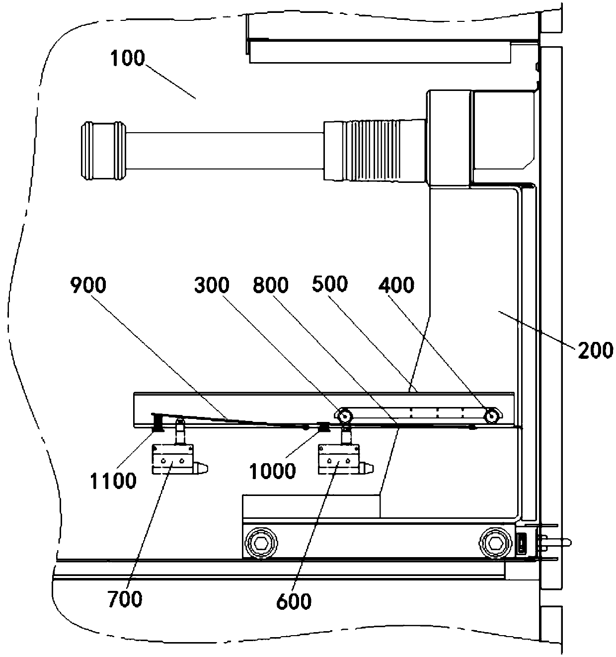
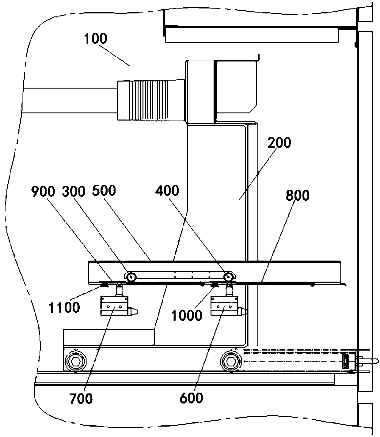
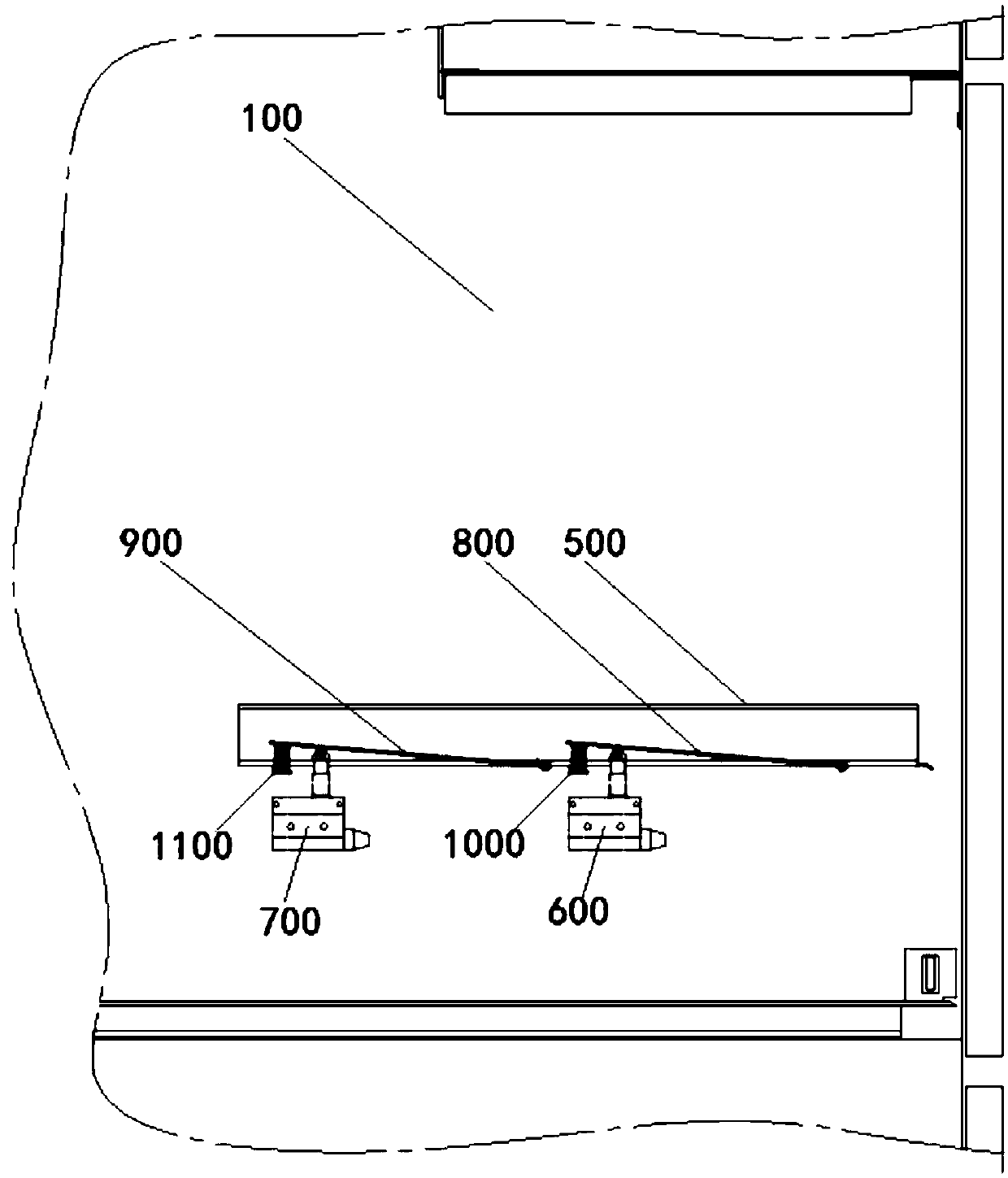
[0017] See Figure 1 to Figure 4 As shown, the figure shows a position monitoring device for a switch cabinet grounding handcart, which includes a switch compartment 100 in which a grounding handcart 200 and a pulley guide rail 500 are provided.

[0018] A front pushing pulley 300 is provided on the front end of the grounding handcart 200 on the pulley guide 500, and a rear pushing pulley 400 is provided on the rear end of the grounding handcart 200 on the pulley guide 500; on the pulley guide 500 A front pressing bar 800 is articulated below the front pressing pulley 300, and a front return spring 1000 is arranged between one end of the front pressing bar 800 and the pulley guide rail 500; a state travel switch 600 is arranged at the front end of the pulley guide 500 below the front pressing bar 800 , Used to monitor whether the grounded handcart 200 i...


PUM


Abstract

The invention discloses a position monitoring device for a grounding handcart of a switch cabinet. The device includes a grounding handcart and a pulley guide rail arranged in a switch cabin. A frontpushing and pressing pulley and a rear pushing and pressing pulley are arranged on the pulley guide rail. A front pressing strip is arranged on the pulley guide rail. A front reset spring is arrangedbetween one end of the front pressing strip and the pulley guide rail. A state stroke switch is arranged at the front end of the pulley guide rail. A rear pressing strip is arranged on the pulley guide rail. A rear reset spring is arranged on one end of the rear pressing strip. A position stroke switch is arranged at the rear end of the pulley guide rail. According to the invention, by utilizing the front pushing and pressing pulley and the rear pushing and pressing pulley mounted on the grounding handcart to push and press the stroke switch so as to trigger a stroke switch joint, whether thegrounding handcart is in the switch cabinet or not, whether the grounding handcart is in a working state or not and whether the grounding handcart is in a testing position or not can be monitored andfed back reliably and state signals concerning to that the handcart is moved out of the switch cabinet can be fed back. Besides, influence from handcarts of other switch cabins can be eliminated. Thedevice provided by the invention meets requirements for error interlocking prevention of all switch cabinets on a bus.

Description

Technical field [0001] The invention relates to a removable switch cabinet, in particular to a position monitoring device for a switch cabinet grounding handcart. Background technique [0002] As the main equipment for receiving and distributing power from the power grid, AC metal armored withdrawable switchgear is widely used in power systems because of its convenient operation, good interchangeability, and high reliability of power supply. Among them, for the convenience and safety of maintenance, the grounded handcart is an indispensable functional handcart equipment. Its purpose is to prevent electric shock accidents caused by false power transmission or switching equipment malfunction during the maintenance period. At present, when the widely-used grounding handcart is used, it is safe and reliable to push in the handcart only when the incoming busbar is really not live. It does not have the ability to check whether the grounding handcart is in the switch cabinet or whether ...

Claims


Application Information

Patent Timeline
Patent Type & Authority Applications(China)
IPC IPC(8): H02B11/167H02B11/10
Inventor 黄江
Owner HUNAN YANNENG SENYUAN ELECTRIC POWER EQUIP
Learn More