
Machining device used for split-type ball bearing and machining method thereof

A technology for processing devices and ball bearings, which is applied in positioning devices, metal processing equipment, metal processing machine parts, etc., can solve the problems of inability to realize two hemispheres into one body, reduced utilization rate of parts materials, and low utilization rate of parts materials. Achieve the effects of convenient and reliable use, increased processing efficiency, and increased utilization of product materials

Inactive Publication Date: 2018-01-12
AECC AVIATION POWER CO LTD
View PDF7 Cites 3 Cited by
  • Summary
  • Abstract
  • Description
  • Claims
  • Application Information

AI Technical Summary

Problems solved by technology

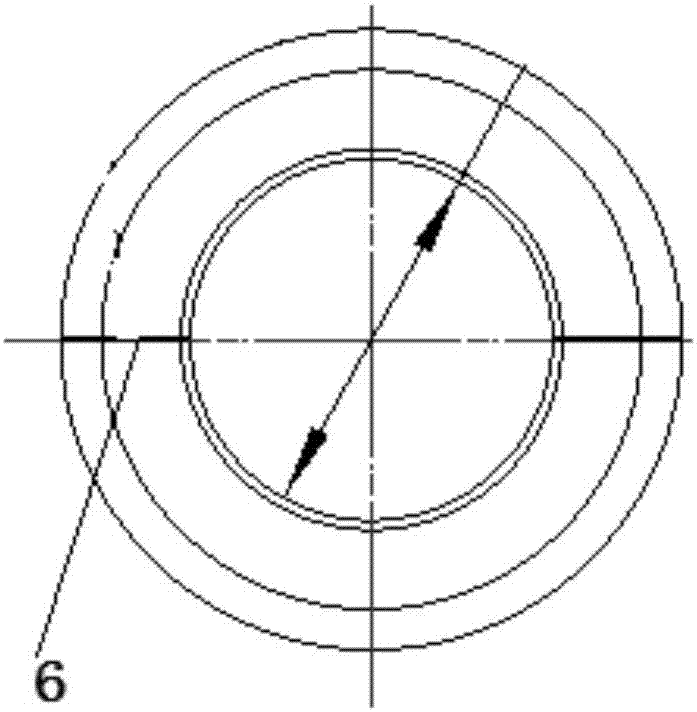
[0002] Aerospace and aerospace split ball bearing parts are used in pairs in actual use. The tolerances of the diameter of the ball and the diameter of the inner hole are required to be precise, and there is a requirement for the gap between the split lines. For specific views, see image 3 The split line 6 shown in the figure, in mechanical processing, in order to ensure the size required by the drawings, it is impossible to realize the two hemispheres into one body. After processing the sphere and the inner hole, it can only be cut and ground to ensure the final drawing requirements. At present, this method is used for processing It is cumbersome, and the utilization rate of parts materials is low. After cutting each sphere, only half can be used, and the other half is scrapped and cannot be used. Therefore, the utilization rate of parts materials is reduced, and the processing efficiency is also greatly reduced.

Method used


Image

  • Machining device used for split-type ball bearing and machining method thereof
  • Machining device used for split-type ball bearing and machining method thereof
  • Machining device used for split-type ball bearing and machining method thereof

Examples


Embodiment Construction

[0027] The present invention is described in further detail below in conjunction with accompanying drawing:

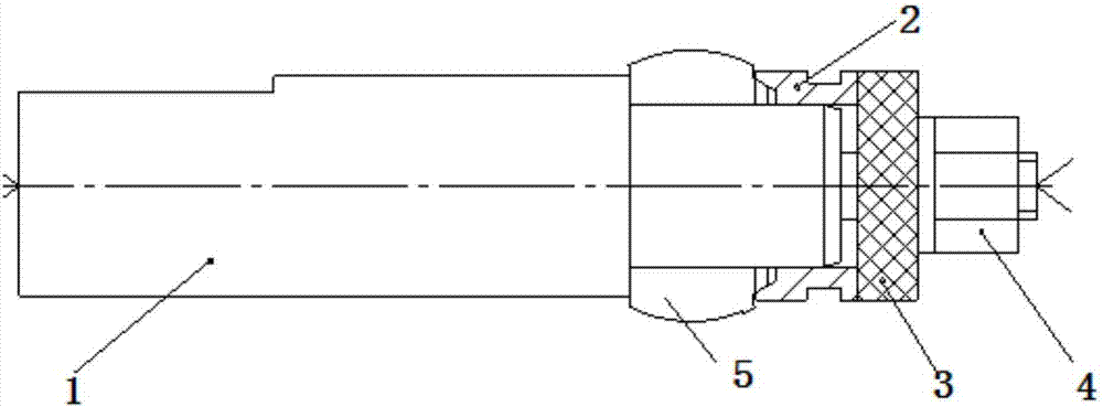
[0028] Such as figure 1 , figure 2 , image 3 As shown, a split ball bearing processing device includes a mandrel 1 for clamping parts 5 to be processed, one end of the mandrel 1 is a stepped shaft, and the stepped shafts of the mandrel 1 are installed in order from large to small The part 5 to be processed, the limit ring 4, the washer 2 and the nut 3, one end of the part 5 to be processed is in contact with the shoulder end face of the mandrel 1, the other end of the part 5 to be processed is in contact with one end of the limit ring 4, and the other end of the limit ring 4 It is in contact with one end of washer 2, and the other end of washer 2 is in contact with one end of nut 3;

[0029] Among them, the parts to be processed are two hemispherical bearings to be processed, that is, split ball bearings to be processed;

[0030] The stepped shaft of mandrel 1 is...


PUM

PropertyMeasurementUnit
thicknessaaaaaaaaaa

Abstract

The invention discloses a machining device used for a split-type ball bearing. A core shaft with one end being a stepped shaft is arranged, and a to-be-machined part, a limiting ring, a gasket and a nut are sequentially mounted on the stepped shaft of the core shaft; one end of the to-be-machined part makes contact with the end face of a shaft shoulder of the core shaft, and the other end of the to-be-machined part makes contact with one end of the limiting ring; and the other end of the limiting ring makes contact with the gasket, and the other end of the gasket makes contact with one end ofthe nut. Two to-be-machined semi-ball bearings are simultaneously clamped by the core shaft with the stepped shaft and then are closely combined through the limiting ring to ensure that jumping of theparts conforms to machining requirements. According to the machining device used for the split-type ball bearing, machining of the two semi-ball bearings in pairs is achieved, the machining device isreliable and safe in using, so that machining efficiency is doubled, and the material utilization of products is increased by one time.

Description

technical field [0001] The invention belongs to the category of mechanical processing fixtures, and in particular relates to a processing device for split ball bearings and a processing method thereof. Background technique [0002] Aerospace and aerospace split ball bearing parts are used in pairs in actual use. The tolerances of the diameter of the ball and the diameter of the inner hole are required to be precise, and there is a requirement for the gap between the split lines. For specific views, see image 3 The split line 6 shown in the figure, in mechanical processing, in order to ensure the size required by the drawings, it is impossible to realize the two hemispheres into one body. After processing the sphere and the inner hole, it can only be cut and ground to ensure the final drawing requirements. At present, this method is used for processing It is cumbersome, and the utilization rate of parts materials is low. After cutting each sphere, only half can be used, and t...

Claims


Application Information

Patent Timeline
Patent Type & Authority Applications(China)
IPC IPC(8): B23P15/00B23Q1/76B23Q3/12
Inventor 李飞涂娇杨能阁辛飞席丽娜张立义智勇王旭科
Owner AECC AVIATION POWER CO LTD
Learn More