Supercharge Your Innovation With Domain-Expert AI Agents!

Flap valve

A technology for flapping door seat and door cover, applied in the field of flapping door, can solve the problems of unsatisfactory counterweight effect, difficulty in opening flapping door, low impact force of water flow, etc., to improve service life, facilitate liquid injection and discharge, Impact reduction effect

Inactive Publication Date: 2018-01-12
YANGZHOU QUNYI MACHINERY CO LTD
View PDF0 Cites 2 Cited by
  • Summary
  • Abstract
  • Description
  • Claims
  • Application Information

AI Technical Summary

Problems solved by technology

In addition, when the internal drainage is low, it is difficult to open the heavy flap door when the impact force of the water flow is low.
[0003] For this reason, someone arranges a cavity in the flap, and injects water into the cavity to increase the weight of the flap cover, so that when the flap is impacted (the impact height is at the lower edge of the flap), the water in the cavity will not only play a role In addition to the counterweight, the water in the cavity will also give an upward impact to the flapper cover, so after use, a large part of the gravity of the water is offset by the upward impact of the water on the flapper cover, so the actual distribution Heavy effect is not ideal

Method used


Image

  • Flap valve

Examples


Embodiment Construction

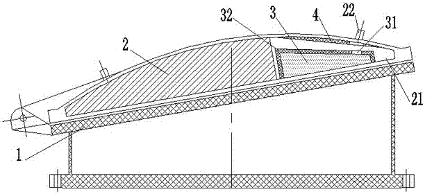
[0018] The present invention comprises a flapper seat 1 and a flapper cover 2 hinged on the flapper seat 1, the flapper cover 2 is obliquely arranged on the flapper seat 1, and the lower end of the flapper cover 2 is a hinged end;

[0019] The upper end of the flap door cover 2 is provided with a cavity 21, and a counterweight device 3 is provided in the cavity 21, and the counterweight device 3 is supported by the bottom surface of the cavity 21, and the counterweight device 3 is incompatible with The top surfaces of the cavities 21 are in contact.

[0020] The counterweight device 3 is a liquid storage tank, and the liquid medium is stored in the liquid storage tank.

[0021] The top surface of the cavity 21 is provided with an elastic layer 4 on the upper part of the counterweight device 3 .

[0022] The counterweight device 3 is provided with a liquid injection port 31 , and the flap cover 2 is provided with a liquid inlet 22 corresponding to the liquid injection port 31 ...


PUM


Abstract

The invention relates to a flap valve comprising a flap valve seat (1) and a flap valve cover (2) hinged to the flap valve seat (1). The flap valve cover (2) is slantwise arranged on the flap valve seat (1); the lower end of the flap valve cover (2) is provided with a hinging end; a cavity (21) is disposed in the upper end of the flap valve cover (2); a weight balance device (3) is disposed in thecavity (21); the weight balance device (3) is supported by the bottom surface of the cavity (21); and the weight balance device (3) does not contact the top surface of the cavity (2). With the weightbalance device disposed in the cavity and the weight balance device has no contact with the top surface of the cavity, so upon water impact to the flap valve (when an impact height is equal to the lower edge of the flap valve), the weight of the weight balance device keeps the flap valve still; and no upward impact is caused to the flap valve cover, so ideal use effect can be achieved.

Description

technical field [0001] The invention relates to a flap door, which is a one-way valve device used in water supply and drainage projects to realize backstop and flow interruption. Background technique [0002] The flap door is a one-way valve installed on the coast of rivers or at the water outlet of the water supply and drainage system pipe. It is opened and closed by the pressure difference between the inside and outside of the flap door cover. , The flap door can be closed automatically, preventing tide water from entering the pipeline, and preventing backflow of sea, river and river water. When the tide comes ashore under the action of the wind, the water on the shore can flow into the river through the flap gate. The present flap door structure is made of flap door cover, flap door seat, and vertical elevation is 3 ~ 5 ° inclination angle, is beneficial to flap door tightly closed under the action of gravity. In actual use, when the impact force of tides and waves is l...

Claims


Application Information

Patent Timeline
IPC IPC(8): F16K15/03F16K17/12
Inventor 江国群潘金权
Owner YANGZHOU QUNYI MACHINERY CO LTD
Features
  • R&D
  • Intellectual Property
  • Life Sciences
  • Materials
  • Tech Scout
  • Unparalleled Data Quality
  • Higher Quality Content
  • 60% Fewer Hallucinations
Learn More