Glass fiber-reinforced plastic underground buried pipe with fault location function
What is Al technical title?
Al technical title is built by PatSnap Al team. It summarizes the technical point description of the patent document.
A technology of fault location and buried pipes, applied in the direction of pipes, rigid pipes, pipeline systems, etc., can solve the problems of waste of resources, untimely detection of pipeline ruptures, and accidents, etc., and achieves easy fault detection, simple wiring, maintenance and disassembly. handy effect
Inactive Publication Date: 2018-01-12
MIANYANG FEIYUAN TECH CO LTD
View PDF5 Cites 0 Cited by
Summary
Abstract
Description
Claims
Application Information
AI Technical Summary
This helps you quickly interpret patents by identifying the three key elements:
Problems solved by technology
Method used
Benefits of technology
Problems solved by technology
[0004] The purpose of the present invention is to provide an underground FRP pipe with fault location function, so as to solve the problem of waste of resources and even accidents caused by untimely detection of pipe rupture in long-distance transportation pipelines
Method used
Image
Click on the blue label to locate the original text in one second.
Reading with bidirectional positioning of images and text.
Examples
Embodiment
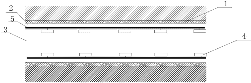
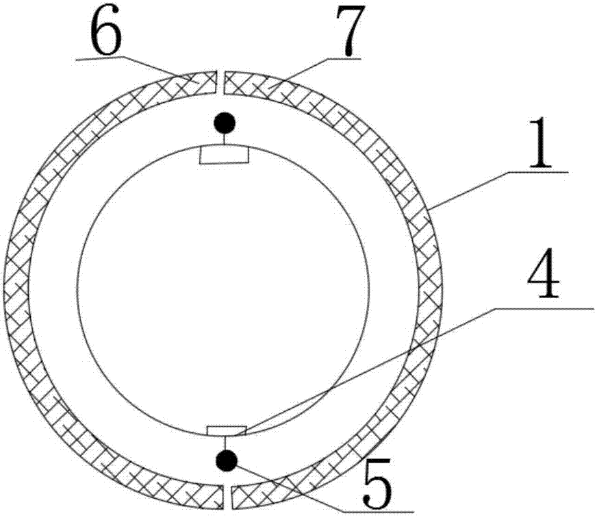
[0025] Such as figure 1 , 2 As shown, the FRP underground pipe with fault location function of the present invention includes a reinforcement layer 1, a FRP layer 2, a delivery pipeline 3, a pressure sensor 4, and a communication optical cable 5. The reinforcement layer 1 is arranged on the outermost side, and the delivery pipeline 3 is arranged In the innermost side, the FRP layer 2 is located between the reinforcement layer 1 and the conveying pipeline 3, the pressure sensor 4 is arranged inside the conveying pipeline 3, the pressure sensor 4 is connected to the communication optical cable 5, and the communication optical cable 5 is arranged in the FRP layer 2 , the number of the pressure sensors 4 is more than 2, and all the pressure sensors 4 are arranged on the inner side of the upper part and the lower part of the conveying pipeline 3, and the positions of the pressure sensors 4 on the inner side of the upper part and the inner side of the lower part are symmetrical, and...
PUM
Abstract
The invention discloses an underground pipeline, and particularly relates to a glass fiber-reinforced plastic underground buried pipe with a fault location function. The glass fiber-reinforced plasticunderground buried pipe comprises a rebar layer, a glass fiber-reinforced plastic layer, a conveying pipeline, pressure sensors and communication optical cables, wherein the rebar layer is arranged on the outermost side; the conveying pipeline is arranged on the innermost side; the glass fiber-reinforced plastic layer is positioned between the rebar layer and the conveying pipeline; the pressuresensors are arranged on the inner side of the conveying pipeline; the pressure sensors are connected with the communication optical cables; and the communication optical cables are arranged in the glass fiber-reinforced plastic layer. The rebar layer of the pipeline is used for resisting pressure, the glass fiber-reinforced plastic layer resists corrosion, the conveying pipeline is fully-filled during conveying, when the pipeline is broken, pressure intensity of liquids or gases at broken parts is decreased, the pressure sensors in the positions sense the change of pressure intensity, information is transmitted through the communication optical cables, workers conveniently detect faults of the pipeline, and the problems that resources are wasted and accidents are caused due to the fact that pipeline breaking is found not timely in long-distance conveying pipelines are solved.
Description
technical field [0001] The invention relates to an underground pipeline, in particular to a fiberglass underground buried pipeline with a fault location function. Background technique [0002] Underground pipelines are pipelines laid underground for transporting liquids, gases or loose solids. In ancient China, underground drainage pipes made of clay have long been used. When the Ming Dynasty established its capital in Beijing, a large number of bricks and stones were used to build underground drainage pipes. It is about 1 meter wide and about 2 meters high. There are many kinds of modern underground pipelines, including circular, oval, semi-elliptical, multi-circular, oval, rectangular (single-hole, double-hole and multi-hole), horseshoe-shaped and other cross-sectional forms, using steel, cast iron, concrete, Reinforced concrete, prestressed concrete, brick, stone, asbestos cement, clay, plastic, glass fiber reinforced plastic (reinforced plastic) and other materials. ...
Claims
Application Information
Patent Timeline
Application Date:The date an application was filed.
Publication Date:The date a patent or application was officially published.
First Publication Date:The earliest publication date of a patent with the same application number.
Issue Date:Publication date of the patent grant document.
PCT Entry Date:The Entry date of PCT National Phase.
Estimated Expiry Date:The statutory expiry date of a patent right according to the Patent Law, and it is the longest term of protection that the patent right can achieve without the termination of the patent right due to other reasons(Term extension factor has been taken into account ).
Invalid Date:Actual expiry date is based on effective date or publication date of legal transaction data of invalid patent.