Large-view-angle aerial imaging apparatus

An aerial imaging and large viewing angle technology, which is applied in optics, instruments, optical components, etc., can solve the problem of small viewing angle range of suspended display objects, and achieve low processing difficulty and overall cost, low processing accuracy requirements, and high pixel density. Effect

Pending Publication Date: 2018-01-12
陈科枫
View PDF3 Cites 5 Cited by
  • Summary
  • Abstract
  • Description
  • Claims
  • Application Information

AI Technical Summary

Problems solved by technology

[0003] However, directly using the above three methods for imaging, there is a problem that the viewing angle range of the floating display object is small

Method used


Image

  • Large-view-angle aerial imaging apparatus
  • Large-view-angle aerial imaging apparatus
  • Large-view-angle aerial imaging apparatus

Examples


Embodiment 2

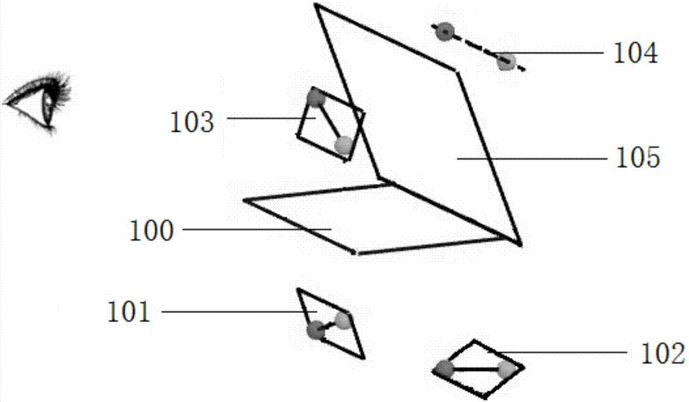
[0052] Such as Figure 14 As shown, a large viewing angle aerial imaging device includes a plane symmetric imaging optical plate 100, two partially transmissive and partially reflective plane mirrors and a display screen, and the two partially transmissive and partially reflective plane mirrors are arranged symmetrically along the plane symmetric imaging optical plate 100. The screen 101 forms a first virtual image 107 through the first partially transmissive and partially reflective plane mirror 106, the first virtual image 107 forms a second image 108 through the plane symmetric imaging optical plate, the first display screen 101 forms the first image through the plane symmetric optical plate 100, and the second The second image 108 forms a third image through the second partially transmissive and partially reflective flat mirror 109, and the third image overlaps with the first image.

Embodiment 3

[0054] Such as Figure 15 As shown, a large viewing angle aerial imaging device includes a plane symmetric imaging optical plate 100 and a display screen 110, the display screen 110 and the fog surface 111 are arranged symmetrically along the plane symmetric imaging optical plate 100, and the display screen is on the plane symmetric imaging optical plate 100 A floating display screen 112 is formed. Specifically, the fog surface is equivalent to the scattering surface. Micro-water droplets can be generated by ultrasonic transducers, fans, heating, pressure spraying, or a combination of several methods to form a fog surface. Scattered light under the optical plate converges to the fog surface area through the optical plate, where it is scattered, so as to achieve the effect of expanding the horizontal and vertical viewing angles.


PUM


Abstract

The invention provides a large-view-angle aerial imaging apparatus, comprising a plane symmetric imaging optical board, a reflector and a plurality of objects; the objects are arranged on one side ofthe plane symmetric imaging optical board, and the objects and the reflector are positioned on two sides of the plane symmetric imaging optical board. The plane symmetric imaging optical board, the objects and the reflector are arranged to superpose images of the objects. The imaging position is provided with a matt face, scattered light below the plane symmetric imaging optical board can be gathered to a matte area by the plane symmetric imaging optical board for the purpose of scattering, and the horizontal view angle and vertical view angle can be further widened.

Description

technical field [0001] The invention relates to the technical field of optical imaging elements, in particular to aerial imaging equipment with a large viewing angle. Background technique [0002] In the prior art, planar symmetric imaging devices mainly fall into the following categories: 1. The divergent light emitted by a luminous object or an optically irradiated object is transmitted through an optical plate composed of a corner reflective array, reflected twice in the optical plate, and then Convergence (imaging) is possible in plane-symmetrical positions with respect to the optical plate. 2. The divergent light emitted by the luminous object or the optically irradiated object is refracted by the microlens array, and converged to form an image at a plane symmetrical position relative to the optical plate. 3. The divergent light emitted by the luminous object or the optically irradiated object passes through the negative refractive index material and converges to form ...

Claims


Application Information

Patent Timeline
Patent Type & Authority Applications(China)
IPC IPC(8): G02B27/22G02B5/08
Inventor 陈科枫
Owner 陈科枫
Why Eureka
Try Eureka