Apparatus for increasing brightness of projection television
A projection TV, high-brightness technology, applied to color TV parts, TV system parts, TVs, etc., can solve the problems of reduced brightness and light transmittance, and achieve vertical and horizontal viewing angles and brightness improvements Effect
- Summary
- Abstract
- Description
- Claims
- Application Information
AI Technical Summary
Problems solved by technology
Method used
Image
Examples
no. 1 example
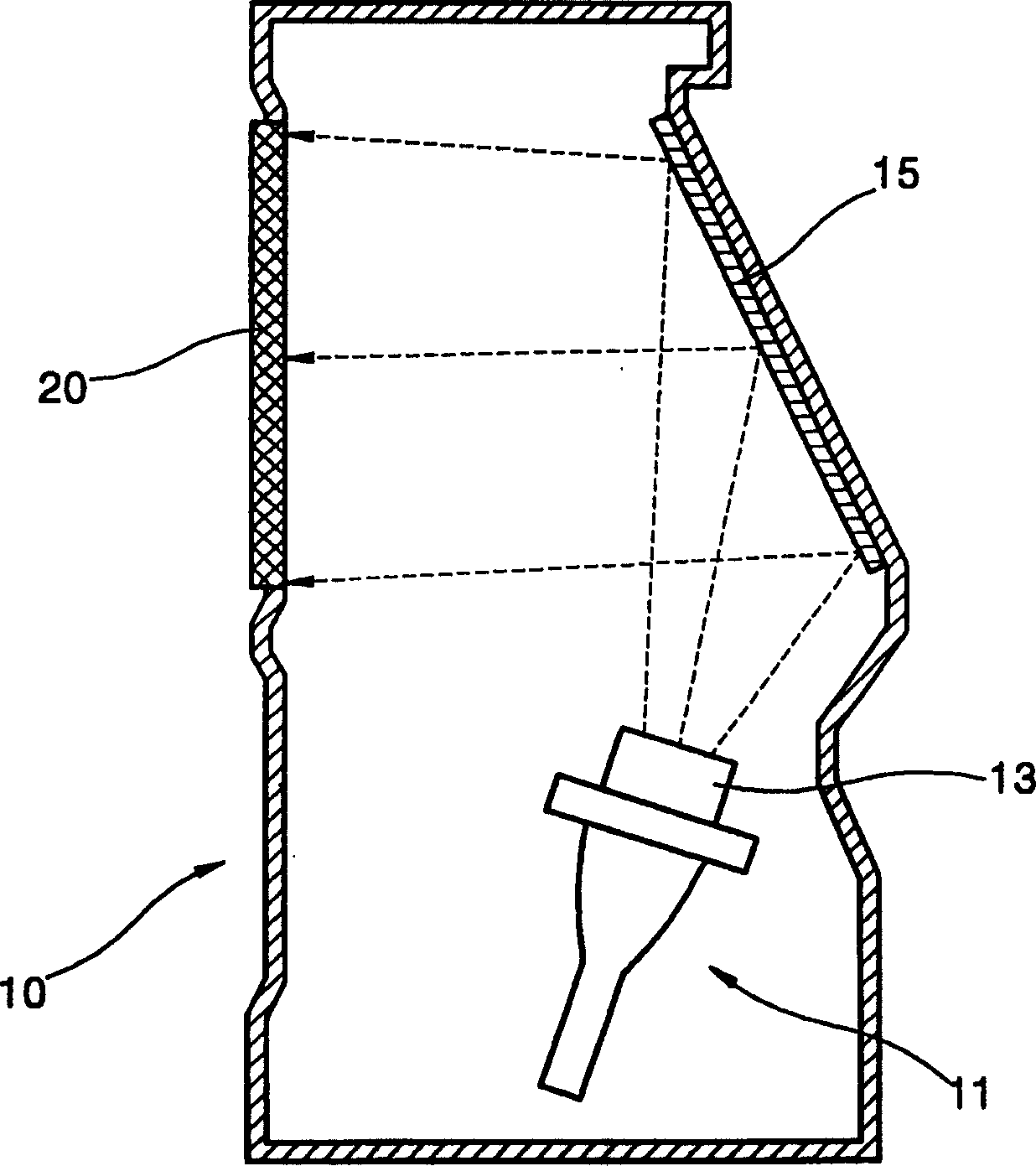
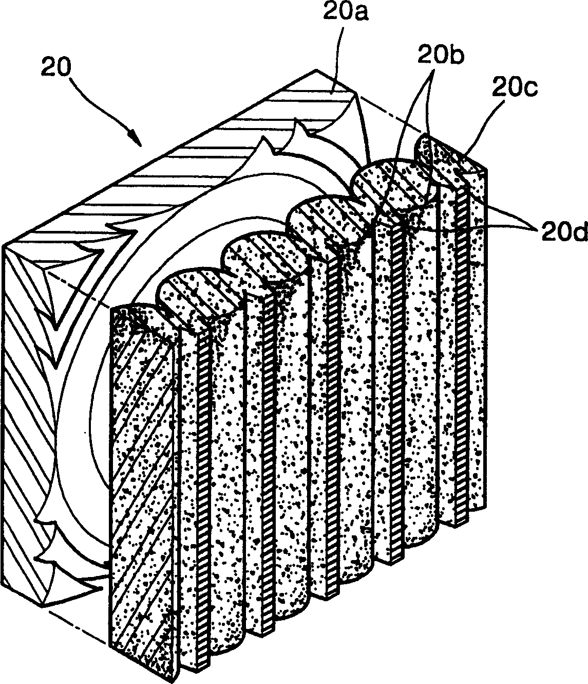
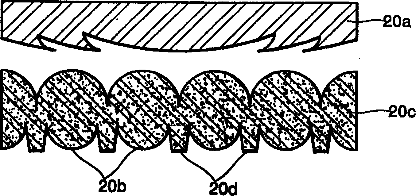
[0033] see Figure 4 According to the first embodiment of the display screen 100 of the high brightness projection television of the present invention, the first lens device 110 and the second lens device 120 are included. The first lens means 110 is arranged to refract the incident light beam into convergent light, and preferably the first lens means 110 is a Fresnel lens, and converts the incident light beam having predetermined image information of the projection means into a parallel light beam. The second lens arrangement 120 is arranged to fold the light beam refracted by the first lens arrangement 110 into a diverging light beam. Preferably, the second lens device 120 is a biconvex lens, in which a plurality of convex unit lenses 121 are connected in parallel. In addition, the parallel connection portion of the unit lens 121 includes a ridge portion 122 . A plurality of black stripes 122 b are formed by printing black ink on the front surface of the ridge portion 122 ...
no. 2 example
[0042] see Image 6 , the light emitting material 124 according to the first embodiment is embedded in the back side of the second lens arrangement 120 adjacent to the first lens arrangement 110 .
[0043] In particular, the light-emitting material 124 is embedded in the convex portion of the second lens device 120 facing the first lens device 110 . Here, the light emitting material 124 is preferably embedded along the surface of the second lens arrangement 120 and evenly distributed from the top to the bottom of the second lens arrangement 120 .
no. 3 example
[0045] A third embodiment of the display screen according to the invention is formed by combining the first and second embodiments. In this case, the light-emitting material 124 is embedded in the light-emitting surface of the second lens device 120 adjacent to the protective plate (not shown) and in the convex portion of the surface of the second lens device 120 adjacent to the first lens device 110 . In this case, it is preferable to arrange the same light-emitting material 124 on both surfaces of the second lens arrangement 120 . However, the fluorescent properties of the light-emitting material 124 embedded in the two surfaces of the second lens arrangement 120 may also be different or somewhat different.
[0046] For example, one kind of fluorescent substance selected from the substance group consisting of red, green and blue fluorescent substances is embedded in the convex portion of the second lens device 120 adjacent to the protective plate, and another fluorescent su...
PUM
 Abstract
Description
Claims
Application Information
 - R&D
- Intellectual Property
- Life Sciences
- Materials
- Tech Scout
- Unparalleled Data Quality
- Higher Quality Content
- 60% Fewer Hallucinations
Browse by: Latest US Patents, China's latest patents, Technical Efficacy Thesaurus, Application Domain, Technology Topic, Popular Technical Reports.
© 2025 PatSnap. All rights reserved.Legal|Privacy policy|Modern Slavery Act Transparency Statement|Sitemap|About US| Contact US: help@patsnap.com


