Offshore wind turbine composite foundation and foundation reinforcement construction method

A composite foundation and offshore wind turbine technology, which is used in foundation structure engineering, soil protection, sheet pile walls, etc. The effect of foundation area, improving structural utilization, and improving vertical and lateral bearing capacity

Active Publication Date: 2020-08-07
HEBEI UNIV OF TECH
View PDF3 Cites 5 Cited by
  • Summary
  • Abstract
  • Description
  • Claims
  • Application Information

AI Technical Summary

Problems solved by technology

[0003] At present, the foundation form of wind turbines in nearshore wind farms is mainly based on single pile foundations. In my country, the seabed soil in some areas contains muddy soft soil and clay layers, especially in highly compressive areas with thick overlying layers. The pile foundation is not easy to stabilize the pile, and the bearing capacity is weak. To obtain sufficient bearing capacity, it is necessary to increase the piling depth to the bearing layer or even make rock-socketed piles, which greatly increases the cost
In order to improve the load-b

Method used


Image

  • Offshore wind turbine composite foundation and foundation reinforcement construction method
  • Offshore wind turbine composite foundation and foundation reinforcement construction method
  • Offshore wind turbine composite foundation and foundation reinforcement construction method

Examples


Example Embodiment

[0028] The present invention will be described in further detail below with reference to the drawings and specific embodiments. The following embodiments are only descriptive and not restrictive, and the protection scope of the present invention cannot be limited by this.

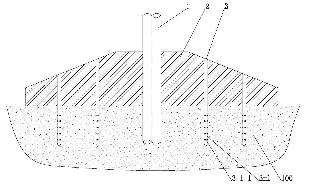
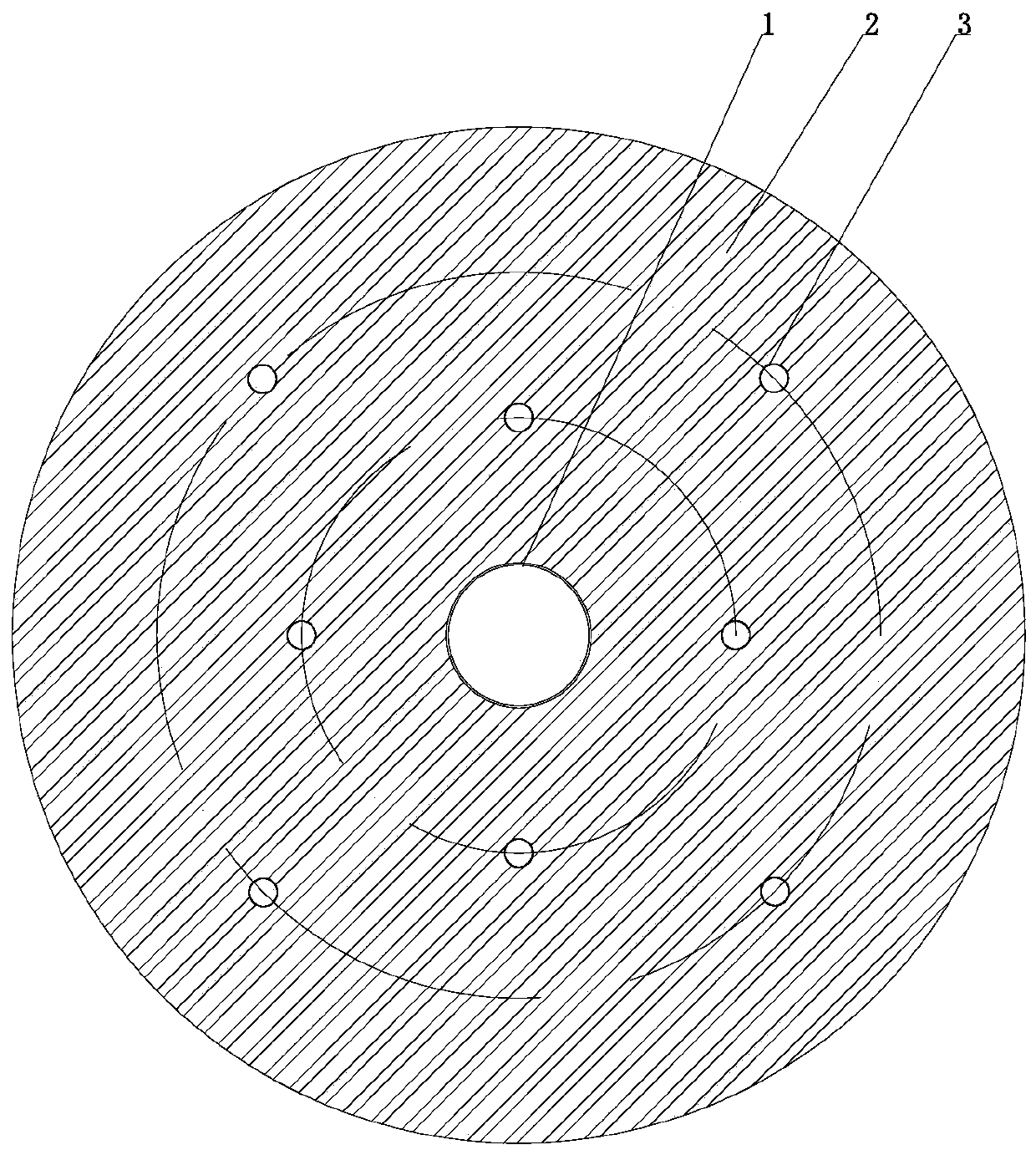
[0029] A composite foundation for offshore wind turbines, see Figure 1-3 , Its invention is:

[0030] It includes a single-pile foundation body 1, which is a hollow steel pipe pile. The lower section of the hollow steel pipe pile is inserted into the foundation soil, and the upper section is exposed above the foundation soil.

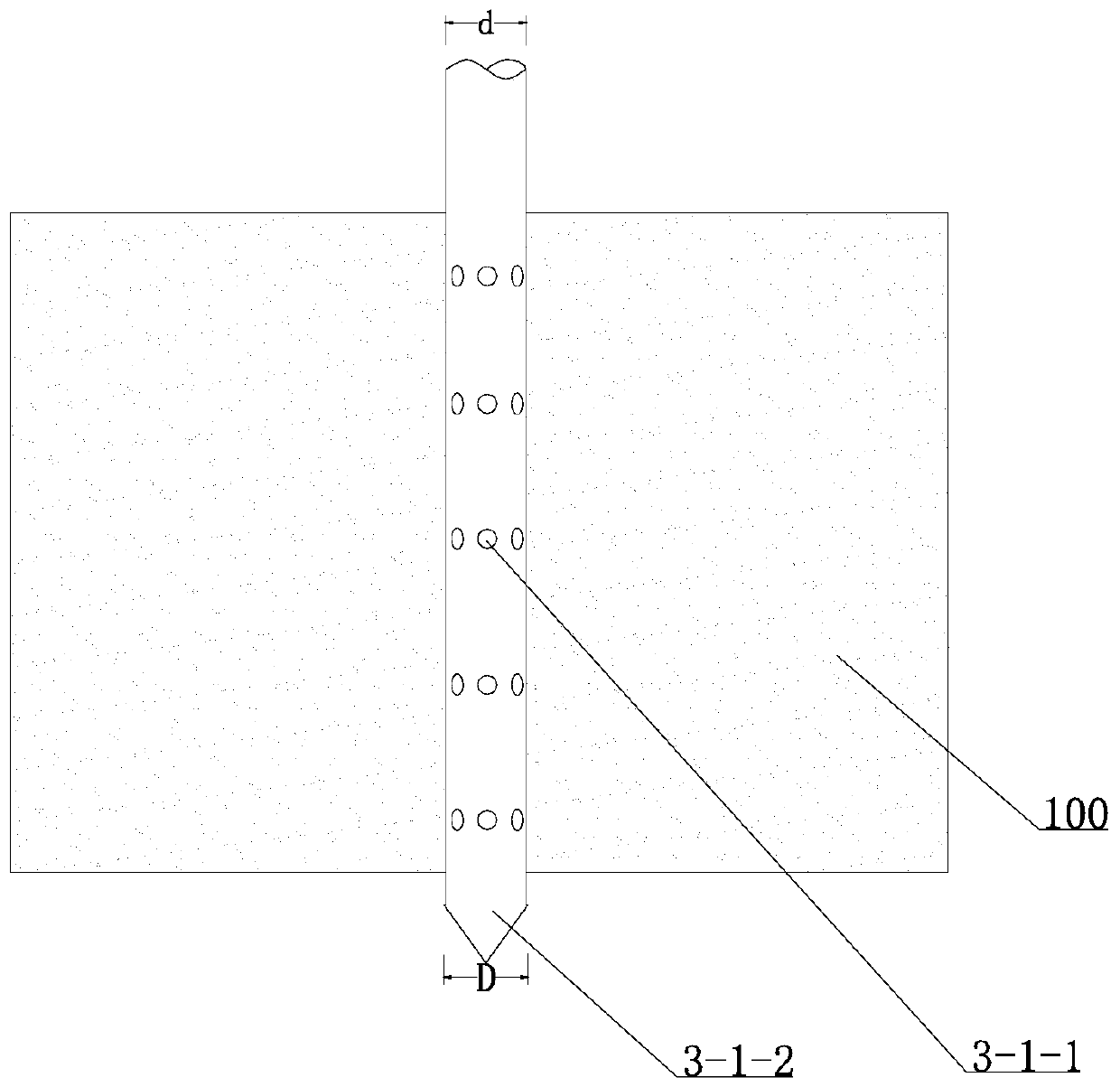
[0031] Including the peripheral friction body 2, which is an integrated concrete pouring structure with built-in steel bars. The shape is a truncated cone. The peripheral friction body is sleeved outside the single pile foundation body and contacts the upper end of the foundation soil. The peripheral friction body is provided with a connection The upper and lower ends are used for groutin...


PUM


Abstract

The invention relates to an offshore wind turbine composite foundation and a foundation reinforcement construction method. The composite foundation comprises a single-pile foundation body and a peripheral friction body, wherein the peripheral friction body is of a concrete integrated pouring structure with built-in steel bars and is in a circular truncated cone shape; the single-pile foundation body is sleeved with the peripheral friction body; the peripheral friction body makes contact with the upper end of a foundation soil body; vertical construction hole channels which communicate the upper end with the lower end and are used for achieving grouting are formed in the peripheral friction body; a plurality of vertical construction hole channels are evenly distributed on one or more circles of circumference; and a steel pipe nail is connected into each vertical construction hole channel in a pouring mode or fixedly inserted into each vertical construction hole channel, the lower section of each steel pipe nail extends out of the lower end of the peripheral friction body and is inserted into the foundation soil body, and guniting holes are evenly distributed in the pipe wall of eachsteel pipe nail. According to the composite foundation, the contact area between the foundation and a subgrade is increased, grouting reinforcement treatment can be conducted on the soft soil foundation, thus the bearing capacity of the subgrade and the foundation can be improved, integrated construction is achieved, and seabed pretreatment is reduced.

Description

technical field [0001] The invention belongs to the technical field of offshore wind turbine foundations, and in particular relates to a composite foundation for offshore wind turbines and a foundation reinforcement construction method. Background technique [0002] According to the survey results of wind energy, within the range of 5-25m and 2-50m in my country's offshore areas, the development potential of offshore wind power at heights of 50m and 70m has reached 200 million and 500 million kilowatts, respectively. The deep sea area is even more limitless. Due to the limitation of land resources, the development of offshore wind energy is in full swing around the world. Offshore wind turbine foundations include fixed and floating foundation structures. The specific foundation types include: monopile foundation structure, jacket foundation structure, tripod foundation structure, gravity foundation structure, column foundation structure, tension leg foundation structure, Se...

Claims


Application Information

Patent Timeline
IPC IPC(8): E02D27/42E02D15/04E02D3/12E02D5/28
CPCE02D3/12E02D5/28E02D15/04E02D27/425
Inventor 王雪菲李家乐马成良
Owner HEBEI UNIV OF TECH
Why Eureka
Try Eureka