Apparatus for increasing brightness of projection television

A projection TV and projection technology, applied in the parts of color TVs, TV systems, TVs, etc., can solve the problems of decreased light transmittance and reduced brightness, and achieve vertical and horizontal viewing angles increase and brightness improve. Effect

Inactive Publication Date: 2003-07-02
SAMSUNG ELECTRONICS CO LTD
View PDF0 Cites 8 Cited by
  • Summary
  • Abstract
  • Description
  • Claims
  • Application Information

AI Technical Summary

Problems solved by technology

[0010] According to the conventional display screen, although the viewing angle is increased by the diffuser, the ligh

Method used


Image

  • Apparatus for increasing brightness of projection television
  • Apparatus for increasing brightness of projection television
  • Apparatus for increasing brightness of projection television

Examples


no. 1 example

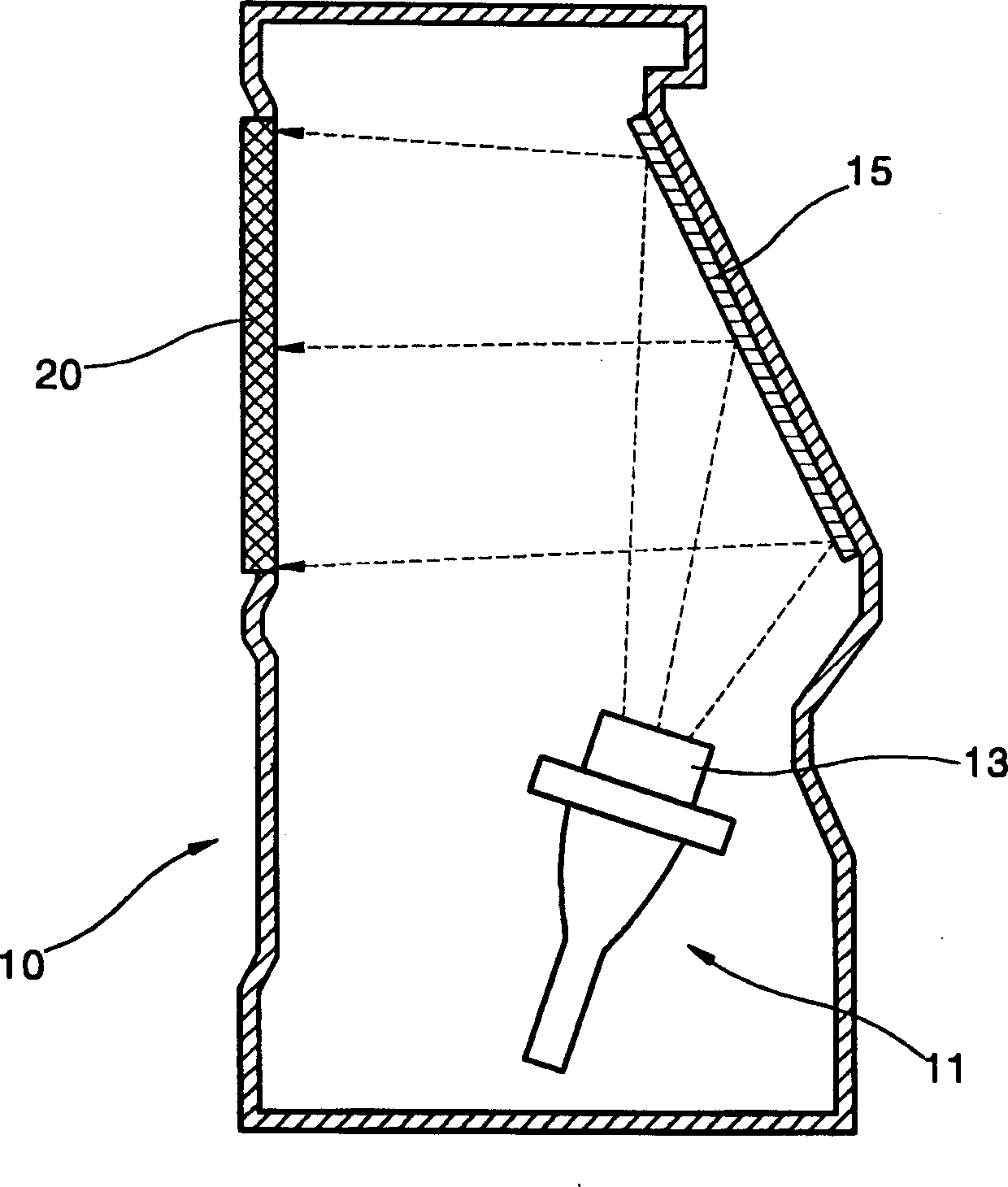
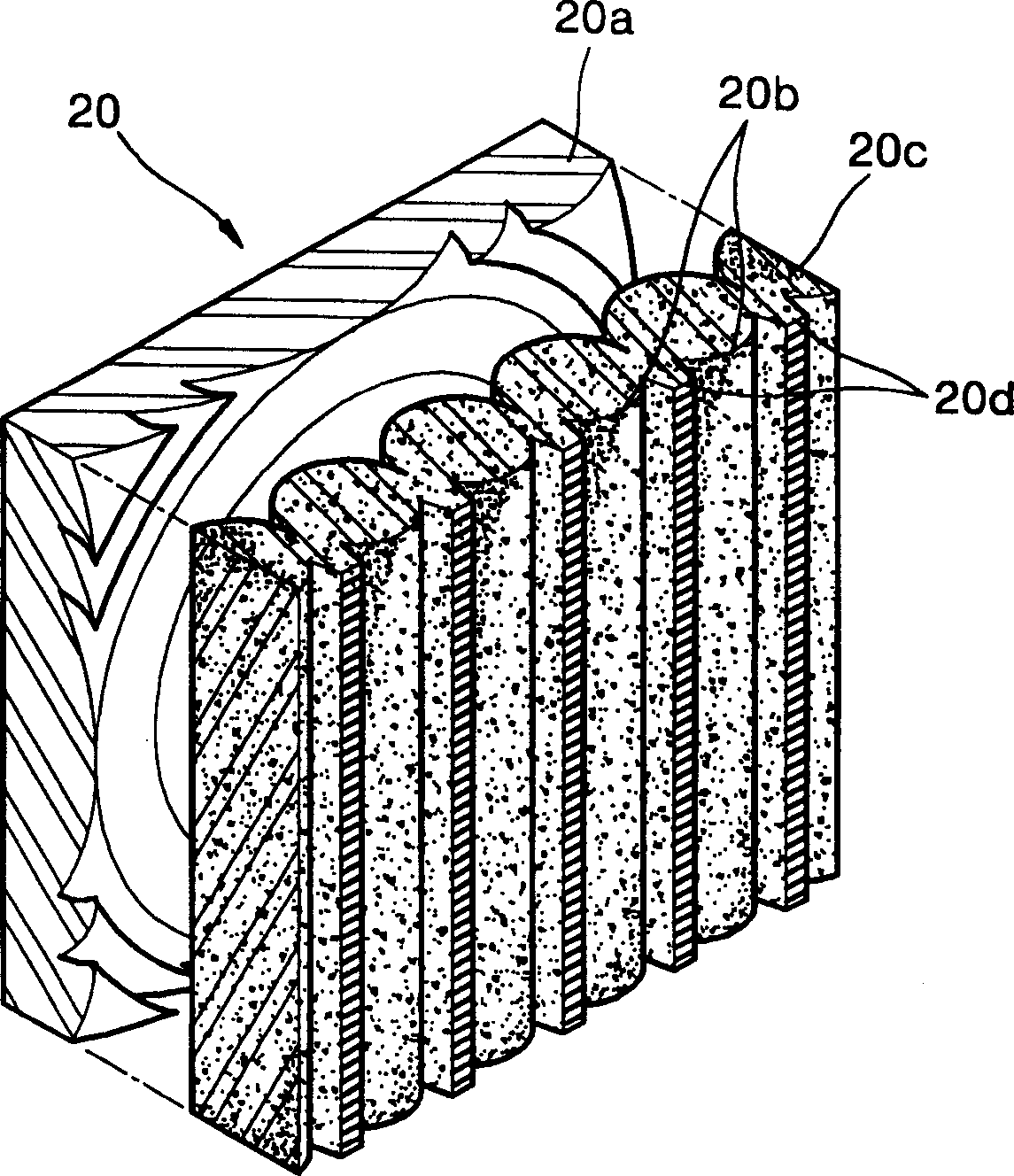
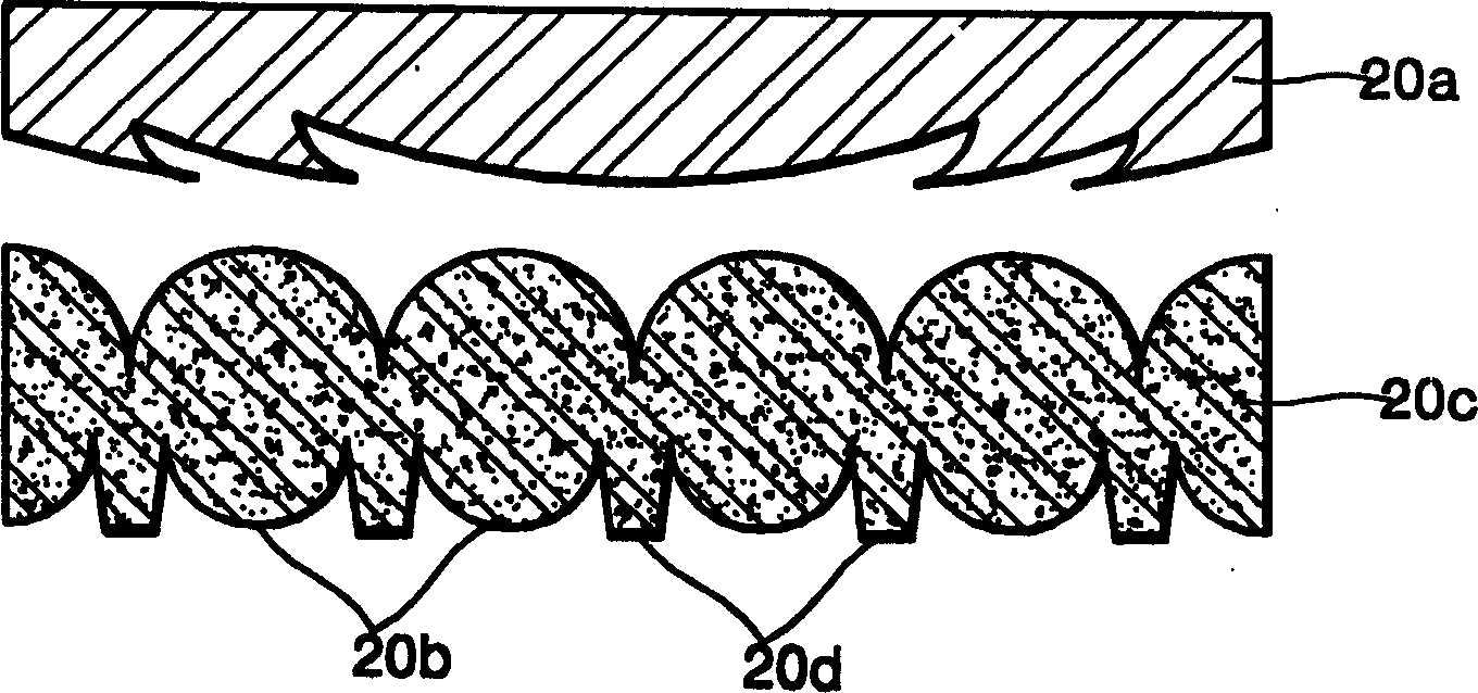
[0032] see Figure 4 According to the first embodiment of the display screen 100 of the high brightness projection television of the present invention, the first lens device 110 and the second lens device 120 are included. The first lens means 110 is arranged to refract the incident light beam into convergent light, and preferably the first lens means 110 is a Fresnel lens, and converts the incident light beam having predetermined image information of the projection means into a parallel light beam. The second lens arrangement 120 is arranged to fold the light beam refracted by the first lens arrangement 110 into a diverging light beam. Preferably, the second lens device 120 is a biconvex lens, in which a plurality of convex unit lenses 121 are connected in parallel. In addition, the parallel connection portion of the unit lens 121 includes a ridge portion 122 . A plurality of black stripes 122 b are formed by printing black ink on the front surface of the ridge portion 122 ...

no. 2 example

[0041] see Figure 6 , the light emitting material 124 according to the first embodiment is embedded in the back side of the second lens arrangement 120 adjacent to the first lens arrangement 110 .

[0042] In particular, the light-emitting material 124 is embedded in the convex portion of the second lens device 120 facing the first lens device 110 . Here, the light emitting material 124 is preferably embedded along the surface of the second lens arrangement 120 and evenly distributed from the top to the bottom of the second lens arrangement 120 .

no. 3 example

[0044] A third embodiment of the display screen according to the invention is formed by combining the first and second embodiments. In this case, the light-emitting material 124 is embedded in the light-emitting surface of the second lens device 120 adjacent to the protective plate (not shown) and in the convex portion of the surface of the second lens device 120 adjacent to the first lens device 110 . In this case, it is preferable to arrange the same light-emitting material 124 on both surfaces of the second lens arrangement 120 . However, the fluorescent properties of the light-emitting material 124 embedded in the two surfaces of the second lens arrangement 120 may also be different or somewhat different.

[0045] For example, one kind of fluorescent substance selected from the substance group consisting of red, green and blue fluorescent substances is embedded in the convex portion of the second lens device 120 adjacent to the protective plate, and another fluorescent su...


PUM


Abstract

A high-brightness projection television is provided which includes a screen having a first lens for refracting an incident beam into a convergent beam, a second lens for refracting the beam refracted by the first lens into a divergent beam, and a protection plate for protecting at least the second lens, wherein an optical emission material is included in at least one of the above elements to convert invisible lights included in the incident beam into visible lights. Alternatively, the projection television may include an optical emission layer having the optical emission material between a light source and an image generator such as a liquid crystal display (LCD). Accordingly, vertical and horizontal angles of view are increased and overall brightness of the image is improved.

Description

technical field [0001] The present invention relates to a projection television, and more particularly, to a projection television having increased brightness, achieving high brightness while widening the horizontal and vertical viewing angles. Background technique [0002] Image displays such as projection televisions and video projectors generate images by using image generating devices such as small-sized cathode ray tubes (CRT), liquid crystal displays, and polymer diffused liquid crystals (PDLC) as image sources, enlarge and project the images to the large screen to display the desired image. The demand for projection TVs and video projectors is increasing due to the advantage of providing large-sized images. [0003] Image projection systems are classified into front projection and rear projection according to their methods of enlarging and projecting images to a screen. [0004] see figure 1 , a conventional rear-projection projection TV includes a casing 10, a dis...

Claims


Application Information

Patent Timeline
IPC IPC(8): G02F1/13G02F1/1335G02F1/13357G03B21/10G03B21/62G03B21/625H04N5/74
CPCG03B21/625G03B21/10H04N5/7441H04N9/3141H04N5/74
Inventor 尹锡溢黄奎焕
Owner SAMSUNG ELECTRONICS CO LTD
Why Eureka
Try Eureka