Swing mechanism and multifunctional machine

A swing mechanism and transmission component technology, applied in the field of power tools, can solve problems such as low strength and short service life, and achieve the effects of high strength, small size, and reduced vibration and noise

Pending Publication Date: 2018-01-16
POSITEC POWER TOOLS (SUZHOU) CO LTD
View PDF32 Cites 1 Cited by
  • Summary
  • Abstract
  • Description
  • Claims
  • Application Information

AI Technical Summary

Problems solved by technology

[0005] Therefore, the technical problem to be solved by the present invention is to overcome the unreasonable disadvantages of low strength, short service life, and inability to connect working accessories to quickly replace the structure of the swing mechanism of the prior art multifunctional machine, thereby providing a device that can eliminate noise and Vibration, but also to ensure the strength of parts, long service life, the swing mechanism that can connect the working accessories to quickly replace the structure has a multi-function machine with this swing mechanism

Method used


Image

  • Swing mechanism and multifunctional machine
  • Swing mechanism and multifunctional machine
  • Swing mechanism and multifunctional machine

Examples


Embodiment 1

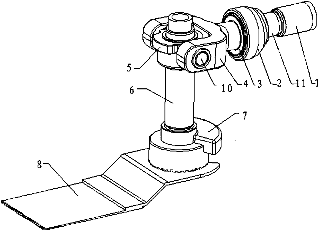
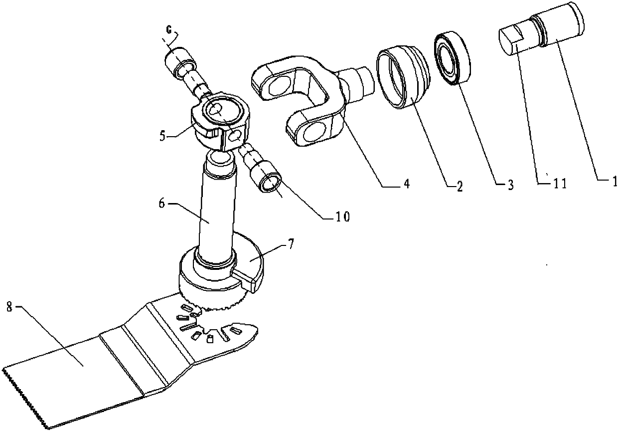
[0038] see Figure 1-3 As shown, the swing mechanism of Embodiment 1 includes

[0039] The drive shaft 1 rotates under the drive of the power structure;

[0040] The output shaft 6 is set at an angle with the drive shaft 1, and is used for installing working accessories;

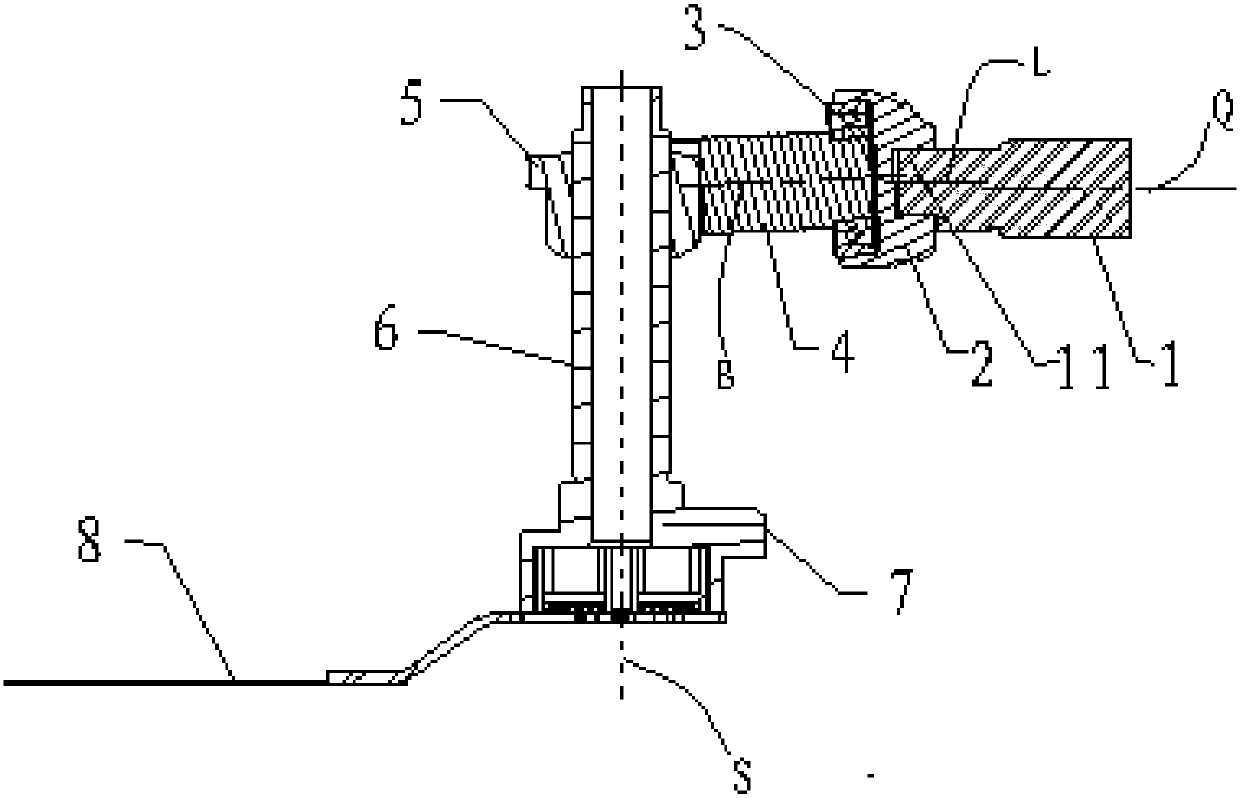
[0041] The swing transmission mechanism is connected between the drive shaft 1 and the output shaft 6, and has a transmission member and a toggle assembly; the transmission member is connected to the drive shaft 1; the first end of the toggle assembly connected to the transmission member, the second end is rotatably connected to the output shaft around the pivot axis G, wherein the pivot axis G is perpendicular to the axis of the output shaft 6 (ie the output shaft axis S), And pass through the intersection of the drive shaft 1 and the output shaft axis S; the axis extending from the first end to the second end of the toggle assembly is the toggle axis B, and the toggle Axis B forms an inclination angle w...

Embodiment 2

[0052] The difference between Embodiment 2 and Embodiment 1 lies in the structure of the toggle piece and the connection method between the toggle piece and the bearing, specifically: the toggle piece is a shift fork, and the main body is a shift fork sleeve; The transmission member is an eccentric member, and the eccentric member includes an eccentric part 2 connected with the drive shaft 1 and a bearing 3 arranged outside the eccentric part 2, and one end of the drive shaft 1 is connected to the bearing 3 The axis of the fork is coaxially inserted into the bearing 3, and the shift fork sleeve is sleeved outside the bearing 3.

Embodiment 3

[0054] The difference between Embodiment 2 and Embodiment 1 lies in the structure of the follower and the position of the follower on the output shaft, specifically: the follower has a through cavity, and the side of the through cavity There is a through hole on the wall, the upper end of the output shaft is inserted into the through hole, and the space in the through cavity is suitable for connecting the functional part to the upper end of the output shaft.

[0055] Such as Figure 4 As shown, a multifunctional machine of the present invention includes a casing, a power structure arranged in the casing, and a swing mechanism driven by the power structure is connected to the output shaft 6 of the swing mechanism, and the swing mechanism is driven by the swing mechanism. The working attachment 8 is driven by a swing mechanism, and the swing mechanism is the above-mentioned swing mechanism. Usually the power structure is a motor. Because the multifunctional machine of the pres...


PUM


Abstract

The invention provides a swing mechanism and a multifunctional machine. The swing mechanism includes a drive shaft, an output shaft, a transmission member, and a stirring assembly; the transmission member is connected to the drive shaft; a first end of the stirring assembly is connected to the transmission member, and a second end of the stirring assembly is rotatably connected to the output shaftaround an axis of a pivot shaft; the axis of the pivot shaft is perpendicular to an axis of the output shaft and passes through an intersection point between the axes of the drive shaft and the output shaft; a stirring axis of the stirring assembly and the axis of the drive shaft form a dip angle, and the stirring assembly rotates around the axis of the drive shaft; and the transmission member ispositioned outside of a cross section profile perpendicular to the axis of the drive shaft, of the output shaft. The multifunctional machine has the swing mechanism, can reduce vibration and noise during a working process, is compact in structure, is high in strength, is long in service life, and can conveniently install a working accessory quick change structure.

Description

technical field [0001] The invention relates to the field of power tools, in particular to a multifunctional machine with a swing mechanism. Background technique [0002] The multi-function machine is a kind of oscillating power tool, also known as the oscillating machine, universal treasure, etc. Its working principle is mainly to rotate the shift fork within a certain deflection angle (0.5-7 degrees) through the rotation of the eccentric element (usually an eccentric bearing) at the front end of the motor, and connect different working head working accessories to work, according to the working accessories Different output and different line speed to achieve cutting, grinding and other purposes. [0003] Patent document GB2202025A discloses a right-angle oscillating drive device, including a motor, an eccentric bearing assembly eccentrically mounted on the motor shaft, a toggle shaft inserted into the eccentric bearing assembly at the tail, and an output shaft of the right...

Claims


Application Information

Patent Timeline
Patent Type & Authority Applications(China)
IPC IPC(8): B25F5/00
Inventor 徐静涛
Owner POSITEC POWER TOOLS (SUZHOU) CO LTD
Why Eureka
Try Eureka