

SPI bus hardware triggering and decoding method based on oscilloscope
A technology of SPI bus and decoding method, which is applied in the direction of instruments, digital variable display, electrical digital data processing, etc. It can solve the problems of slow software decoding speed and many software and hardware interactions, achieve fast and accurate triggering and decoding, and reduce waiting time , Improve the effect of long decoding time
- Summary
- Abstract
- Description
- Claims
- Application Information
AI Technical Summary
Problems solved by technology
Method used
Image

Examples
Embodiment 1
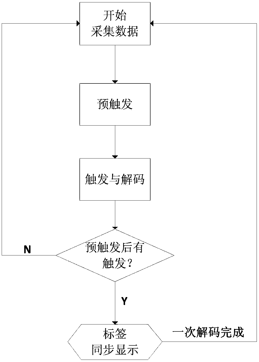
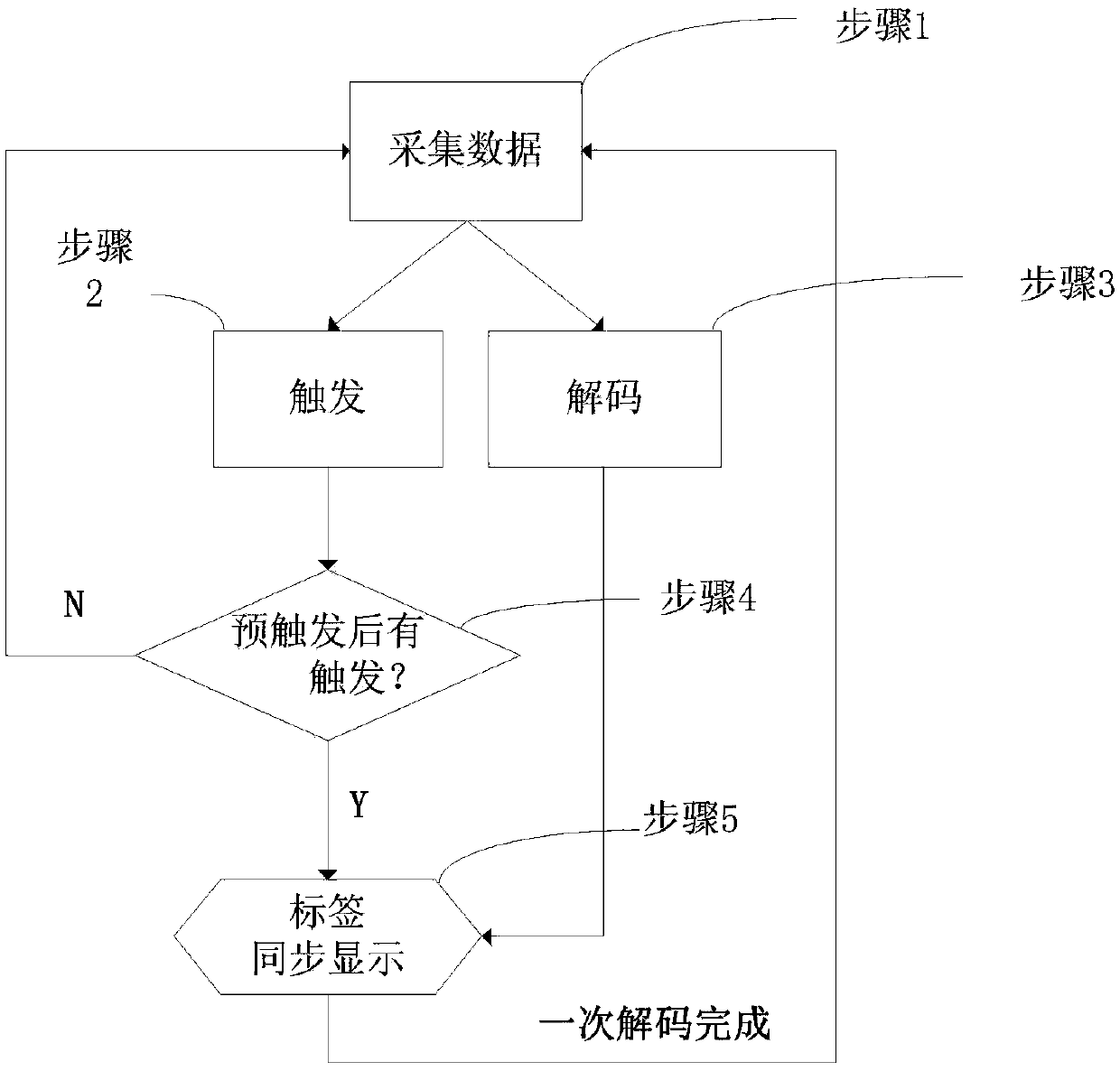
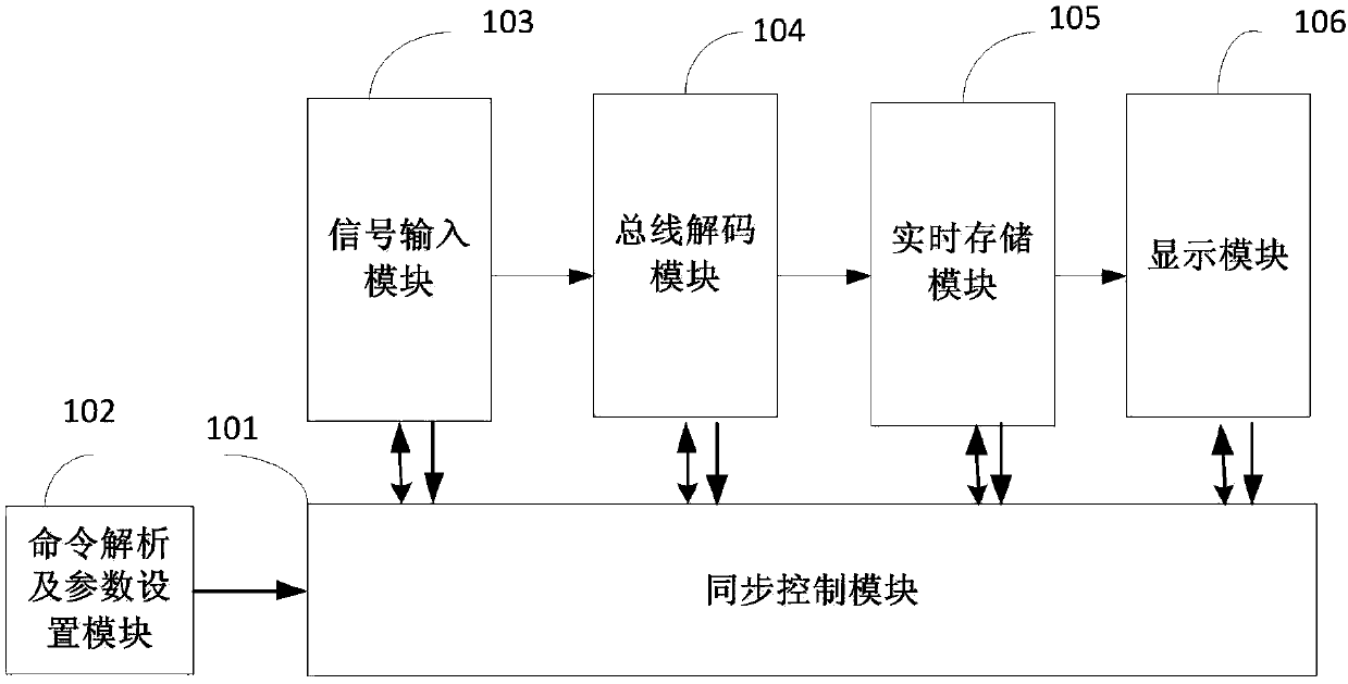
[0026] The present invention is based on the oscilloscope platform and realizes the structure of SPI bus triggering and decoding by hardware as follows: image 3 As shown, the triggering and decoding process mainly includes 6 parts. The synchronous control module is connected and communicates with the command analysis and parameter setting module, the signal input module, the bus decoding module, the real-time storage module and the display module respectively.
[0027] 1. Command analysis and parameter setting module
[0028] Send the input channel selection, channel threshold, channel polarity, bit sequence, bus display setting, bus trigger type, bus trigger mode, trigger data length and trigger data to the synchronous control module, and the synchronous control module will pass the setting information to the The decoding process is controlled.
[0029] 2. Signal input processing module
[0030] The SPI bus has four main channels: SCL (clock signal money), SS (chip select...
PUM
 Abstract
Description
Claims
Application Information