
A horizontal multistage rolling ball mill

A rolling ball mill, horizontal technology, applied in the field of metallurgical machinery, can solve the problems of difficulty in obtaining uniform particle size materials, time-consuming and labor-intensive ball milling effect, and shortening the ball milling time of materials, so as to shorten the time used, facilitate screening and separation, and have good ball milling effect Effect

Inactive Publication Date: 2019-02-01
宝鸡正源化工科技股份有限公司
View PDF9 Cites 2 Cited by
  • Summary
  • Abstract
  • Description
  • Claims
  • Application Information

AI Technical Summary

Problems solved by technology

However, the current ball milling equipment distributes the steel balls randomly in the cylinder, and converts the kinetic energy during the rotation of the lifting steel balls into potential energy to pulverize the materials. This method is time-consuming and laborious, and the ball milling effect is poor and time-consuming. A single rotation crushes the material through the contact between the steel ball and the material. It is difficult to shorten the ball milling time of the material, and it is also difficult to obtain a material with uniform particle size.

Method used


Image

  • A horizontal multistage rolling ball mill
  • A horizontal multistage rolling ball mill
  • A horizontal multistage rolling ball mill

Examples


Embodiment Construction

[0017] The following will clearly and completely describe the technical solutions in the embodiments of the present invention with reference to the accompanying drawings in the embodiments of the present invention. Obviously, the described embodiments are only some, not all, embodiments of the present invention. Based on the embodiments of the present invention, all other embodiments obtained by persons of ordinary skill in the art without making creative efforts belong to the protection scope of the present invention.

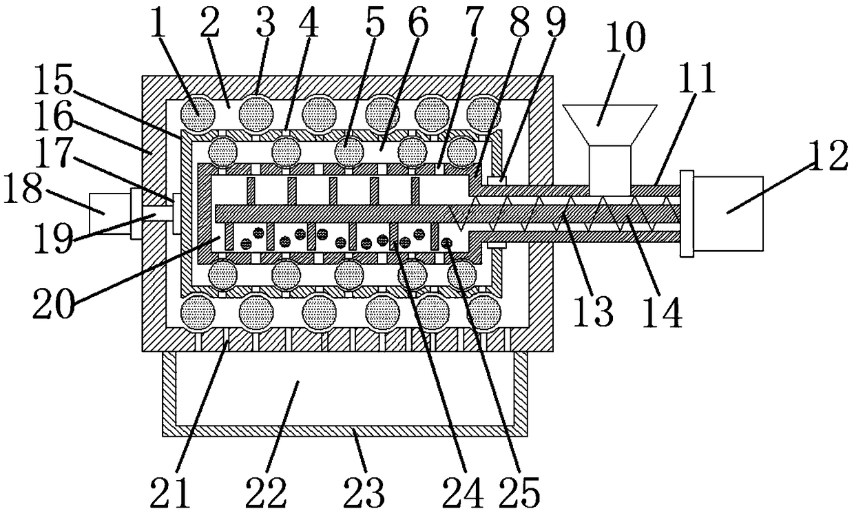
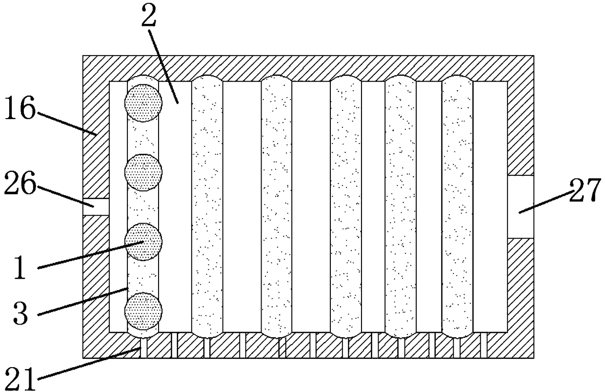
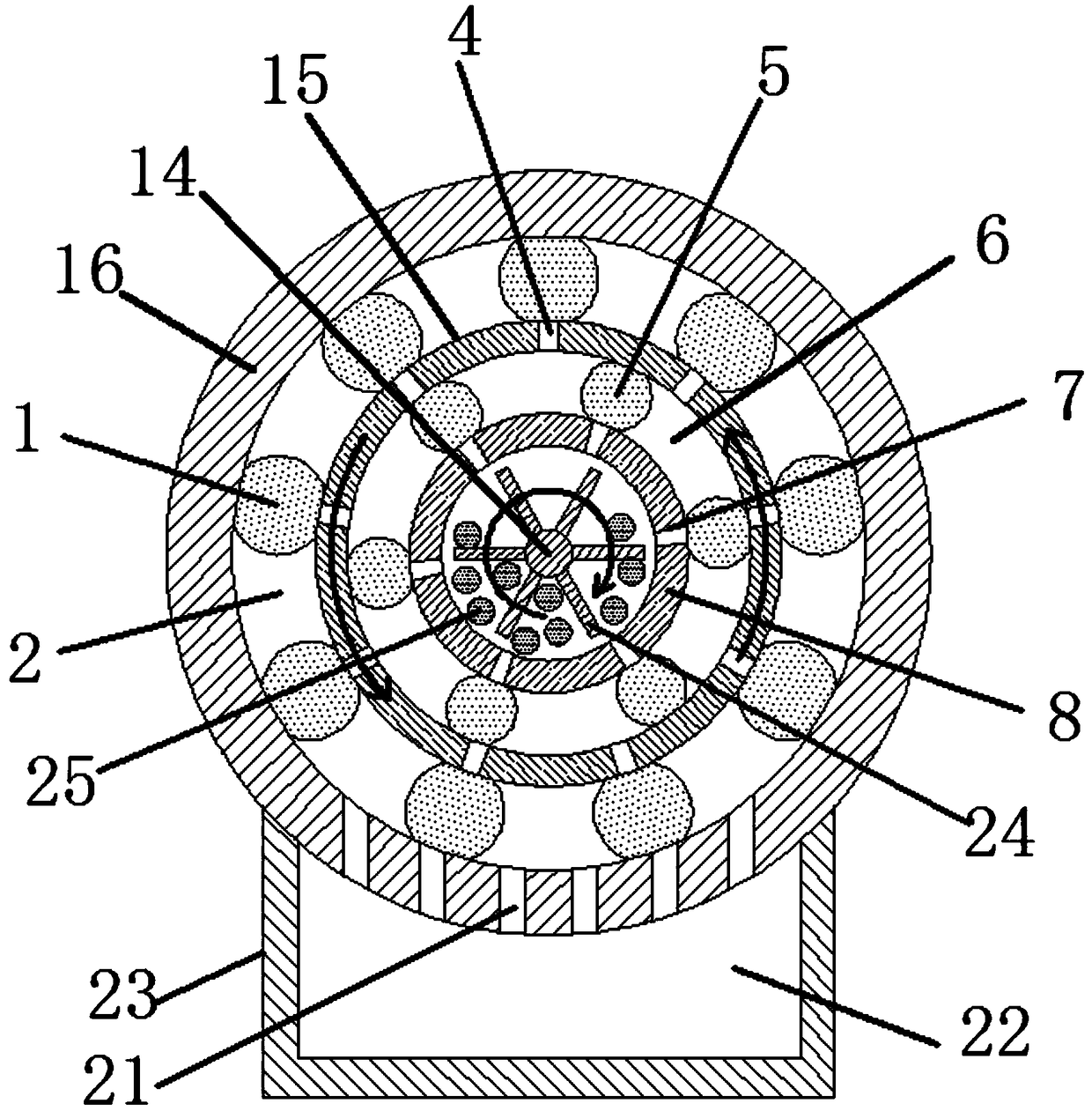
[0018] see Figure 1~3 , in an embodiment of the present invention, a horizontal multi-stage rolling ball mill includes an inner ball mill cylinder 8, a feeding cylinder 11, a rolling ball mill cylinder body 15 and an outer ball mill cylinder 16, and an inner ball mill cylinder is installed inside the outer ball mill cylinder 16 8. One end of the inner ball mill cylinder 8 is welded with a feed cylinder 11. The feed cylinder 11 passes through the feed through ...


PUM


Abstract

The invention discloses a horizontal type multistage rolling ball grinder. The horizontal type multistage rolling ball grinder comprises an inner ball grinding barrel, a feeding barrel, a rolling ballgrinding barrel body and an outer ball grinding barrel, wherein the inner ball grinding barrel is arranged in the outer ball grinding barrel; the feeding barrel is welded at one end of the inner ballgrinding barrel; a plurality of stirring bars are welded on a rotating shaft arranged in the inner ball grinding barrel; a primary ball grinding cavity is formed in the inner ball grinding barrel; aplurality of grinding balls are put in the primary ball grinding cavity; the rolling ball grinding barrel body is arranged between the inner ball grinding barrel and the outer ball grinding barrel; aninner ball grinding cavity is formed between the rolling ball grinding barrel body and the inner ball grinding barrel; a plurality of inner grinding balls are arranged in the inner ball grinding cavity; an outer ball grinding cavity is formed between the rolling ball grinding barrel body and the outer ball grinding barrel; and a plurality of outer grinding balls are arranged in the outer ball grinding cavity. The horizontal type multistage rolling ball grinder has the beneficial effects that the plurality of grinding balls are used for impacting materials to carry out primary ball grinding treatment; the inner grinding balls are used for secondary ball grinding treatment; the outer ball grinding cavity is used for secondary ball grinding treatment; the ball grinding effect is good; the time of ball grinding is shortened; the materials with uniform particle sizes are obtained; and the sieving and separation of the materials subjected to ball grinding are facilitated.

Description

technical field [0001] The invention relates to the technical field of metallurgical machinery, in particular to a horizontal multistage rolling ball mill. Background technique [0002] The ball mill is a kind of equipment for crushing materials. Its basic principle is to use the rotating force to lift the steel balls in the drum, and crush the materials through the contact between the steel balls and the materials. However, the current ball milling equipment distributes the steel balls randomly in the cylinder, and converts the kinetic energy during the rotation of the lifting steel balls into potential energy to pulverize the materials. This method is time-consuming and laborious, and the ball milling effect is poor and time-consuming. It is difficult to shorten the ball milling time of the material, and it is difficult to obtain the material with uniform particle size. Therefore, there is a need for a horizontal multi-stage rolling ball mill to achieve multi-stage ball m...

Claims


Application Information

Patent Timeline
Patent Type & Authority Patents(China)
IPC IPC(8): B02C17/10B02C17/16B02C17/18B02C23/02B02C23/10B02C23/16
CPCB02C17/10B02C17/16B02C17/18B02C17/183B02C17/184B02C17/1855
Inventor 李盼君
Owner 宝鸡正源化工科技股份有限公司
Learn More