
Automatic turning system for battery cells

A technology of automatic flipping and battery cells, which is applied in secondary battery manufacturing, sustainable manufacturing/processing, climate sustainability, etc., can solve problems such as high cost and complex structure of cleaning equipment, so as to ensure the quality of batteries, good automatic Cleaning effect, good cleaning effect

Active Publication Date: 2018-01-19
HUIZHOU CHENGTAI AUTOMATION TECH CO LTD
View PDF6 Cites 5 Cited by
  • Summary
  • Abstract
  • Description
  • Claims
  • Application Information

AI Technical Summary

Problems solved by technology

The cleaning equipment disclosed in the invention realizes fast cleaning of the tabs to a certain extent, and also improves the cleaning quality, but the cleaning equipment of the invention is complex in structure and high in cost

Method used


Image

  • Automatic turning system for battery cells
  • Automatic turning system for battery cells
  • Automatic turning system for battery cells

Examples


Embodiment 1

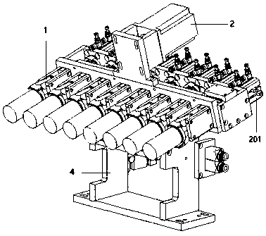
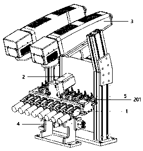
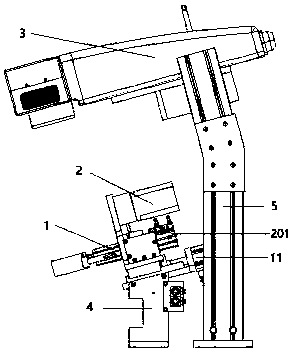
[0038] Such as figure 1 , 2 , 4, and 5, the present embodiment discloses an automatic cell overturning system, which includes an overturn mechanism for realizing the overturn of the cell and a clamping mechanism for clamping the cell during the overturn; the clamping mechanism includes Eight clamping assemblies 1, and a drive assembly for controlling the expansion and contraction of the clamping assembly; the clamping assembly includes a connecting rod 101 and a clamping claw, and one end of the connecting rod 101 is connected to the clamping claw, and the other end is connected to the drive components.

[0039]By setting the overturning mechanism and the clamping mechanism, when it is applied to the tab cleaning equipment, the overturning mechanism will automatically turn over the battery cell by 180 degrees, and the clamping mechanism will hold the battery core during the overturning, so as to realize the complete alignment of the tabs. Azimuth cleaning.

[0040] The clam...

Embodiment 2

[0057] Such as figure 1 , 3 , 4, and 5, the present embodiment discloses an automatic cell overturning system, which includes an overturning mechanism for realizing the overturning of the cell and a clamping mechanism for clamping the cell during the overturn; the clamping mechanism includes 4 clamping assemblies, and a driving assembly for controlling the expansion and contraction of the clamping assembly; the clamping assembly includes a connecting rod 101 and a clamping claw, one end of the connecting rod is connected to the clamping claw, and the other end is connected to the driving assembly.

[0058] By setting the overturning mechanism and the clamping mechanism, when it is applied to the tab cleaning equipment, the overturning mechanism will automatically turn over the battery cell by 180 degrees, and the clamping mechanism will hold the battery core during the overturning, so as to realize the complete alignment of the tabs. Azimuth cleaning.

[0059] The clamping c...


PUM


Abstract

The invention discloses an automatic turning system for battery cells. The automatic turning system for the battery cells comprises a turning mechanism used for turning the battery cells and a clamping mechanism used for clamping the battery cells when the battery cells are turned. The clamping mechanism comprises one or more clamping assemblies and a driving assembly used for controlling the clamping assemblies to stretch and retract. Each clamping assembly comprises a connecting rod and a clamping jaw, wherein one end of the connecting rod is connected with the clamping jaw, and the other end of the connecting rod is connected with the driving assembly. As the turning mechanism and the clamping mechanism are arranged, when the automatic turning system for the battery cells is applied toelectrode cleaning equipment, the turning mechanism can automatically turn the battery cells by 180 degrees, the clamping mechanism can clamp the battery cells in the turning process, and thus omnibearing cleaning of electrodes is achieved.

Description

technical field [0001] The invention relates to the technical field of battery lug cleaning, in particular to a battery automatic turning system applied in battery lug automatic cleaning equipment. Background technique [0002] Cylindrical series power cells have many advantages such as excellent safety performance, long cycle life, environmental protection, and excellent power performance. As one of the excellent clean energy sources, it has become an important member of the new energy field. With the vigorous development of electric vehicles based on clean energy at home and abroad, the market demand for cylindrical series power cells is huge, but the requirements for their safety and performance have also increased accordingly. [0003] In the production process of the existing cylindrical series power cells, liquid is first injected into the cells and then the cap is welded; during the liquid injection process, the positive tab is completely immersed in the electrolyte,...

Claims


Application Information

Patent Timeline
Patent Type & Authority Applications(China)
IPC IPC(8): B08B13/00B08B7/00H01M10/04
CPCY02E60/10Y02P70/50
Inventor 张中黄向东何茂水马益金
Owner HUIZHOU CHENGTAI AUTOMATION TECH CO LTD
Learn More