Culvert-type vertical take-off and landing lifting body unmanned aerial vehicle

A technology of vertical take-off and landing and lifting body, which is applied to vertical take-off and landing aircraft, rotorcraft, motor vehicles, etc., can solve the problems of reduced operational safety of unmanned aerial vehicles, increased flight speed, and hazards to surrounding personnel, etc. The effect of the weight of the body structure, increasing the loading space, and increasing the flight speed

Inactive Publication Date: 2018-01-19
CHINA HELICOPTER RES & DEV INST
View PDF5 Cites 29 Cited by
  • Summary
  • Abstract
  • Description
  • Claims
  • Application Information

AI Technical Summary

Problems solved by technology

Since the propulsion device of the tilt-rotor UAV needs to take into account both the take-off and landing and the forward flight state, the size of the rotor is large, and the resistance is relatively large in the forward flight mode, which affects the improvement of the flight speed.
[0006] Moreover, the rotor of the rotor UAV is exposed, and it is easy to collide with obstacles when operating at low altitude, resulting in a decrease in the safety of the UAV operation; and the exposed rotor is a potential hazard to surrounding personnel, and there are potential safety hazards

Method used


Image

  • Culvert-type vertical take-off and landing lifting body unmanned aerial vehicle
  • Culvert-type vertical take-off and landing lifting body unmanned aerial vehicle

Examples


Embodiment Construction

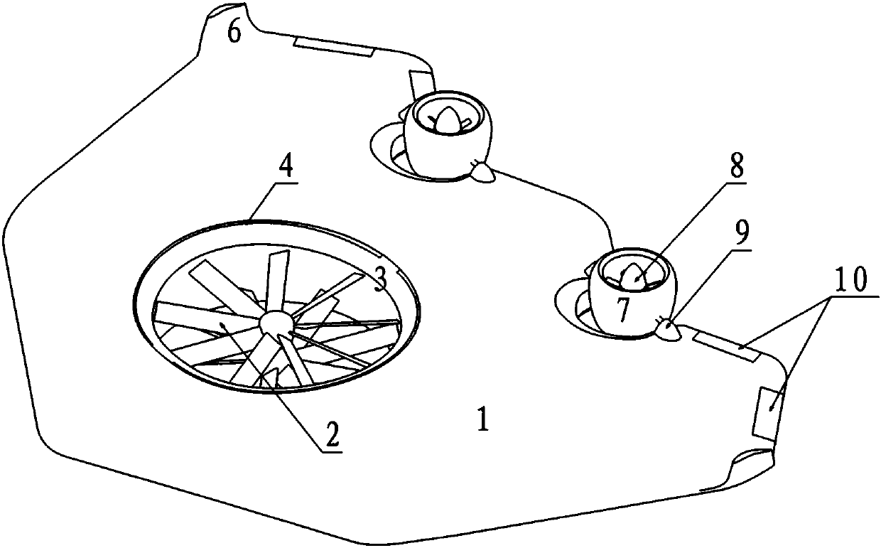
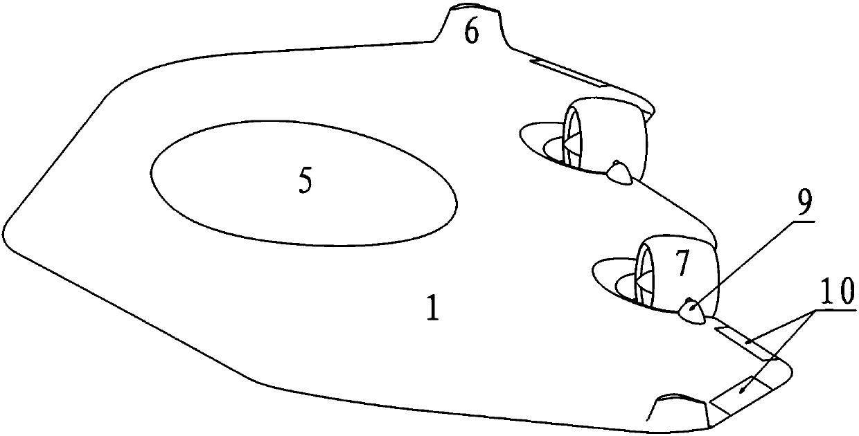
[0032] In order to make the objectives, technical solutions, and advantages of the implementation of the present invention clearer, the technical solutions in the embodiments of the present invention will be described in more detail below in conjunction with the accompanying drawings in the embodiments of the present invention. In the drawings, the same or similar reference numerals indicate the same or similar elements or elements with the same or similar functions. The described embodiments are part of the embodiments of the present invention, rather than all of the embodiments. The embodiments described below with reference to the accompanying drawings are exemplary, and are intended to explain the present invention, but should not be construed as limiting the present invention. Based on the embodiments of the present invention, all other embodiments obtained by those of ordinary skill in the art without creative work shall fall within the protection scope of the present inv...


PUM


Abstract

The invention discloses a culvert-type vertical take-off and landing lifting body unmanned aerial vehicle and relates to the technical field of vertical take-off and landing unmanned aerial vehicles.The culvert-type vertical take-off and landing lifting body unmanned aerial vehicle comprises a fuselage (1), lifting force rotor wings (2), a take-off and landing culvert (3), tilting-rotating thrustculverts (7) and tilting-rotating thrust rotor wings (8). The take-off and landing culvert (3) is composed of a through hole penetrating through the upper surface and the lower surface of the fuselage (1), and the lifting force rotor wings (2) are arranged in the take-off and landing culvert (3). The tilting-rotating thrust culverts (7) are hinged to the rear end of the fuselage (1) through tilting-rotating control mechanisms (9), the tilting-rotating control mechanisms (9) are configured to be capable of enabling the included angle between the axis of each tilting-rotating thrust culvert (7)and the axis of the fuselage (1) to be variable, and the tilting-rotating thrust rotor wings (8) are arranged in the tilting-rotating thrust culverts (7). Under the conditions that the vertical take-off and landing capacity of the unmanned aerial vehicle is maintained and the overall weight of the unmanned aerial vehicle is not excessively increased, the flight speed of the unmanned aerial vehicle is increased, the flight stability of the unmanned aerial vehicle is improved, the rotor wing exposed problem is avoided through the culverts, and the flight safety and the take-off and landing hovering efficiency are improved.

Description

Technical field [0001] The invention belongs to the technical field of vertical take-off and landing rotary wing drones, and specifically relates to a ducted vertical take-off and landing lift-body drone. Background technique [0002] Rotor-type UAVs have vertical take-off and landing capabilities. They don’t need to rely on the launching device or runway required by fixed-wing UAVs when flying. They have a wide range of applications, but they have high forward resistance and low flight speed. Rotor-type UAVs It mainly includes unmanned helicopters, multi-rotor drones and tilt-rotor drones. Fixed-wing UAVs have the advantage of fast forward speed, but take off and landing rely on launchers or taxi tracks, and their application range is not as good as that of rotor UAVs. [0003] Unmanned helicopters include single-rotor with tail rotor configuration, coaxial double-rotor configuration, horizontal double-rotor configuration, tandem double-rotor configuration and other configuration...

Claims


Application Information

Patent Timeline
Patent Type & Authority Applications(China)
IPC IPC(8): B64C27/28B64C29/00
Inventor 刘衍涛
Owner CHINA HELICOPTER RES & DEV INST
Why Eureka
Try Eureka