Working method of propeller-rotor composite configuration tilt rotorcraft

A technology for a tiltrotor and a working method, applied in the field of aircraft, can solve the problems of inability to further increase the flight speed, low hovering efficiency, and large resistance, and achieve the effects of reducing weight, increasing vertical performance, and reducing forward flight resistance.

Pending Publication Date: 2022-02-01
南京华航翼飞行器技术有限公司
View PDF6 Cites 0 Cited by
  • Summary
  • Abstract
  • Description
  • Claims
  • Application Information

AI Technical Summary

Problems solved by technology

[0005] In order to solve the problems in the prior art, the present invention provides a working method for a tiltrotor of a propeller-rotor compound configuration, which can effectively overcome the excessive load on the paddle disk in the vertical mode of the rotor of a conventional tiltrotor. , the hovering efficiency is low, and the rotor diameter is too large and the blades are too soft when flying forward, so that the efficiency is low and the resistance is large, and the flight speed cannot be further increased. The vertical take-off and landing performance is effectively improved, and the rotor is stopped and folded, Significantly increase the speed of forward flight, and achieve the best power matching for different flight states through the propeller-rotor compound power device

Method used


Image

  • Working method of propeller-rotor composite configuration tilt rotorcraft
  • Working method of propeller-rotor composite configuration tilt rotorcraft
  • Working method of propeller-rotor composite configuration tilt rotorcraft

Examples


Embodiment Construction

[0031] A specific embodiment of the present invention will be further described below in conjunction with the accompanying drawings.

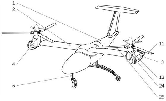
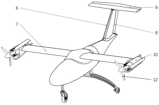
[0032] like Figure 1-2 As shown, the wing 2 is installed on the upper side of the fuselage 1, the T-shaped tail 6 is installed on the rear side of the fuselage 1, the nacelle 3 is installed at the tip of the wing 2, the number is 2, and the composite power unit 4 is installed in the nacelle 3. Internally, the front three-point wheeled landing gear 5 is used, which is installed on the lower part of the fuselage 1, the aileron 7 is installed on the rear edge of the wings 2 on both sides, the rudder 8 is installed on the rear side of the empennage 6, and the elevator 9 is installed on the empennage 6. On the side, the compound power unit 4 is powered by the engine 10, the engine 10 is installed inside the nacelle 3, and is connected with the transmission device 13, and the rotor 11 (including the rotor hub 24 and the rotor blade 25) and the prope...


PUM


Abstract

The invention provides a working method of a propeller-rotor composite configuration tilt rotorcraft. The working method comprises a helicopter mode and a fixed wing mode. In the helicopter mode, the propeller-rotor composite configuration tilt rotorcraft adopts a composite lift force form of rotors and propellers, the propellers provide part of auxiliary lift force, and the rotors provide main lift force. In the fixed wing mode, the propellers are in the front, the rotors are in the rear, the rotors stop rotating and are folded backwards, and lift force is achieved through the wings. The same performance of low-altitude low speed and hovering maneuvering of a rotor type helicopter and the same performance of high-speed forward flying of a fixed wing type airplane are really considered, and the defect that the existing tilt rotorcraft is better than the helicopter in hovering and better than the airplane in forward flying is overcome. The vertical take-off and landing performance is effectively improved, the forward flying speed is remarkably increased through stopping and folding of the rotor wings, and the tilt rotorcraft has wide application prospects in the fields of amphibious landing, material supply, personnel transportation and the like.

Description

technical field [0001] The invention relates to the technical field of aircraft, in particular to a working method of a tilt rotor aircraft with a composite propeller-rotor configuration. Background technique [0002] Tilt rotor aircraft is a new type of aircraft that combines fixed-wing aircraft and helicopters. It not only has the capabilities of vertical take-off and landing, air hovering, etc. of conventional helicopters, but also has the ability of high-speed cruise flight of propeller aircraft. At the tip of the wing of the tilting rotorcraft, each set of rotor tilting system components that can rotate between the horizontal position and the vertical position is installed. When taking off and landing vertically, the rotor axis is perpendicular to the ground, and it is in a helicopter flight state, and Can hover in the air, fly back and forth and sideways. After the tiltrotor takes off and reaches a certain speed, the rotor shaft can be tilted forward at an angle of 90...

Claims


Application Information

Patent Timeline
Patent Type & Authority Applications(China)
IPC IPC(8): B64C27/28B64D35/00B64C1/30
CPCB64C27/28B64D35/00B64C1/30B64C2230/28
Inventor 王振宇朱清峰杨超范瑶朱清华
Owner 南京华航翼飞行器技术有限公司
Why Eureka
Try Eureka