Rope guide with guide rod type adjustable rope guide device and sleeve type rope press

A technology of casing type and rope pressing device is applied in the field of rope guides, which can solve the problems of breaking, breaking or pulling away, electric hoist can not be used, and the structure of the rope guide is fragile, etc., so as to reduce casing wear and have a novel structure. , The effect of strong anti-skew ability

Inactive Publication Date: 2018-01-19
乐弍妹
View PDF0 Cites 2 Cited by
  • Summary
  • Abstract
  • Description
  • Claims
  • Application Information

AI Technical Summary

Problems solved by technology

The inner ring of this kind of rope guide is set on the threaded rope groove outside the reel, and the rope guide is provided with a guide hole, and the wire rope is discharged from it; when the reel rotates, the threaded rope groove drives the rope guide along the drum shaft To move the steel wire rope along the threaded rope groove of the drum neatly; however, the structure of this traditional rope guide is fragile, and the lateral force it can withstand during work is small; in actual work, the steel wire rope cannot be suspended vertically. It often happens that objects are pulled obliquely and dragged obliquely, so that it is easy to break the clamp type rope guide or other guide wheel type rope guides or pull them away from the threaded rope groove on the drum. Once such an accident occurs, When the ground operators found the problem, the wire ropes on the reel were seriously confused, overlapped, and blocked, and the electric hoist had broken down and could not be used; therefore, the traditional rope guide used by the existing electric hoist had obvious problems The defect is one of the main factors of mechanical failure

Method used


Image

  • Rope guide with guide rod type adjustable rope guide device and sleeve type rope press
  • Rope guide with guide rod type adjustable rope guide device and sleeve type rope press
  • Rope guide with guide rod type adjustable rope guide device and sleeve type rope press

Examples


Embodiment approach

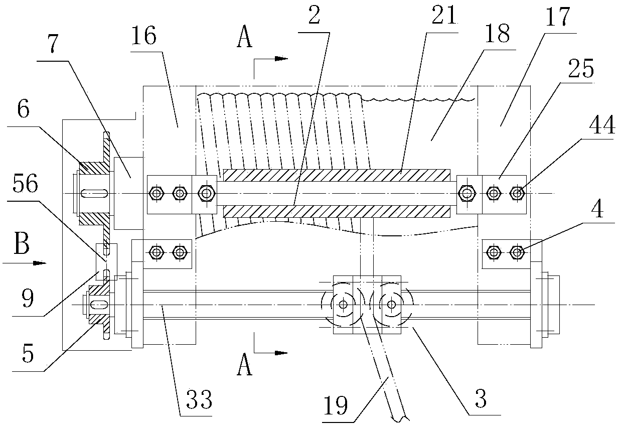
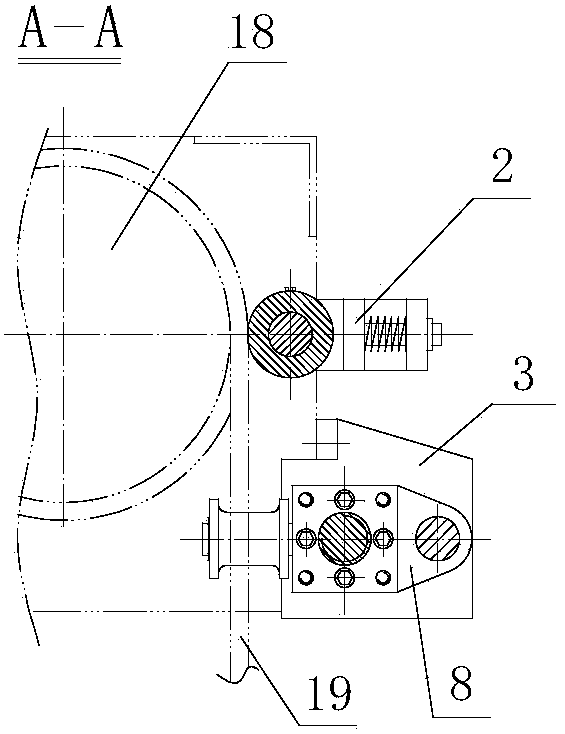
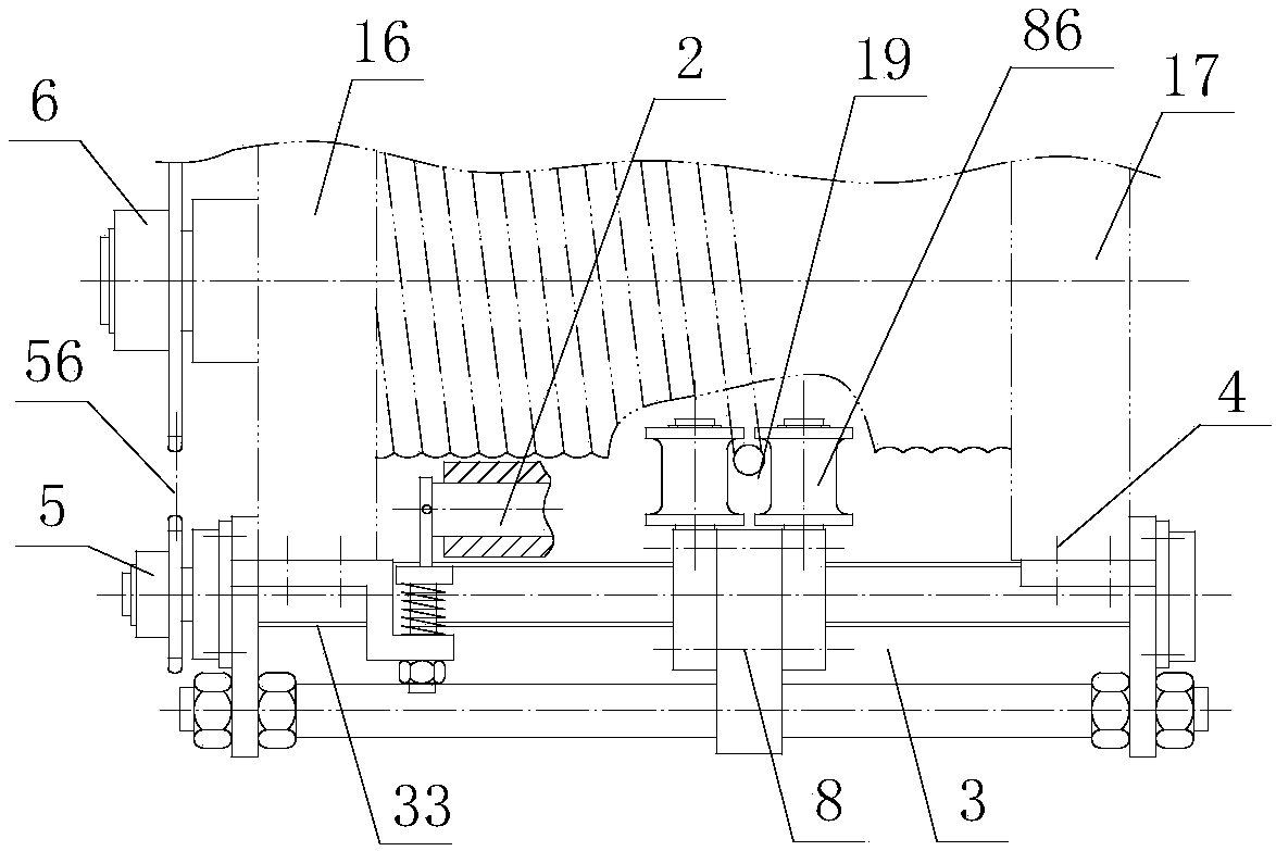
[0021] Such as figure 1 , figure 2 , image 3 As shown, a rope guide with a guide rod type adjustable rope guide device and a sleeve type rope presser is characterized in that it includes a sleeve type rope presser device 2 and a guide rod type thread guide mechanism 3; The fixed seat 25 in the sleeve type rope pressing device 2 is connected to the front of the reel 18 by a bolt 44, and the sleeve 21 on the sleeve type rope pressing device is pressed on the steel wire rope on the drum; the guide rod The threaded guide mechanism 3 is connected to the front of the reel by a bolt 4 and is located below the sleeve type rope pressing device; the guide rod type thread guide mechanism has an adjustable guide rope device 8; the guide rod One end of the threaded shaft 33 on the type thread guide mechanism is connected with the small sprocket 5; the small sprocket is connected with the large sprocket 6 through a chain 56; the large sprocket is connected on the joint shaft 7; the join...


PUM


Abstract

The invention discloses a rope guide with a guide rod type adjustable rope guide device and a sleeve type rope press. The rope guide comprises a sleeve type rope pressing device and a guide rod type threaded guide mechanism, wherein a fixed base in the sleeve type rope pressing device is connected to the front surface of a winding drum through a bolt; a sleeve on the sleeve type rope pressing device is pressed on a steel wire rope on the winding drum; the guide rod type threaded guide mechanism is connected to the front surface of the winding drum through a bolt, and is positioned below the sleeve type rope pressing device; the guide rod type threaded guide mechanism is equipped with an adjustable rope guide device; one end of a threaded shaft on the guide rod type threaded guide mechanismis connected with a small chain wheel; the small chain wheel is connected with a big chain wheel through a chain; the big chain wheel is connected on a joint shaft; the joint shaft is connected to one end of a winding drum shaft of an electric hoist through a bolt; a tightening device is connected on the chain; and a cut-out switch for chain breaking or chain separating is arranged on the tightening device.

Description

technical field [0001] The present application relates to the field of cranes, in particular to a rope guide with a guide rod type adjustable rope guide device and a casing type rope presser. Background technique [0002] The rope guide is an important part of the electric hoist. Its function is to ensure that the wire ropes can be neatly arranged on the reel to prevent the wire ropes from being chaotic, overlapping, etc., which will cause mechanical failure of the electric hoist; most of the existing electric hoists use the clamp type rope guide. The inner ring of this kind of rope guide is set on the threaded rope groove outside the reel, and the rope guide is provided with a guide hole, and the wire rope is discharged from it; when the reel rotates, the threaded rope groove drives the rope guide along the drum shaft To move the steel wire rope along the threaded rope groove of the drum neatly; however, the structure of this traditional rope guide is fragile, and the late...

Claims


Application Information

Patent Timeline
Patent Type & Authority Applications(China)
IPC IPC(8): B66D1/38
Inventor 林记乐弍妹
Owner 乐弍妹
Why Eureka
Try Eureka