Imaging method for longitudinal and transverse radial speed changes

An imaging method and radial velocity technology, applied in shear wave velocity profile, shear wave, can solve problems such as weak universality and high dependence on detection methods when the first broadcast arrives

Active Publication Date: 2018-01-19
BC P INC CHINA NAT PETROLEUM CORP +1
View PDF2 Cites 4 Cited by
  • Summary
  • Abstract
  • Description
  • Claims
  • Application Information

AI Technical Summary

Problems solved by technology

This method is highly dependent on the first broadcast arrival detection method, and there may be various unpredictable noises in the actual logging data. The current first broadcast arrival detection method is not universally applicable to the actual logging data.

Method used


Image

  • Imaging method for longitudinal and transverse radial speed changes
  • Imaging method for longitudinal and transverse radial speed changes
  • Imaging method for longitudinal and transverse radial speed changes

Examples


Embodiment Construction

[0024] The invention will be further described in detail below in conjunction with the accompanying drawings and embodiments, but it is not used as a basis for any limitation on the invention.

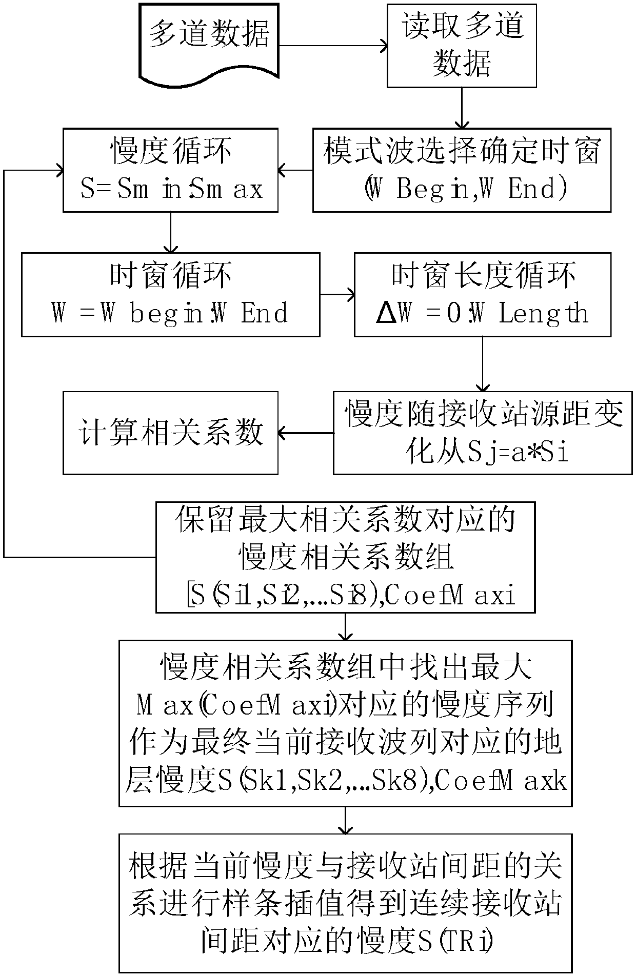
[0025] Such as figure 1 As shown, the imaging method of longitudinal and shear wave radial velocity variation of the present invention comprises the following steps:

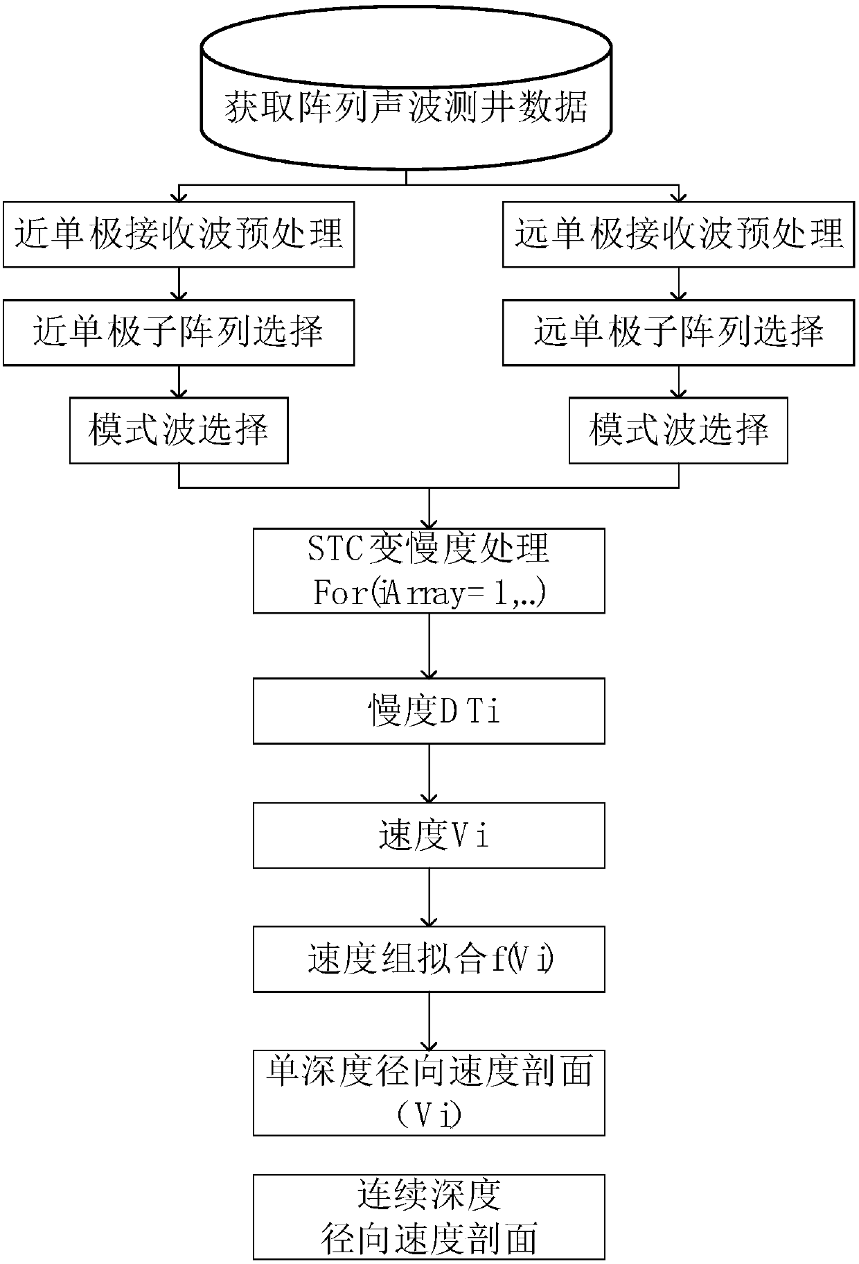
[0026] Step 1, carry out array acoustic well logging, the on-the-spot well logging data that is used for processing analysis mentioned in the present invention comes from a kind of four emission sources, the array acoustic well logging instrument of 8 equisource distance receiving stations (see figure 2 ), the data used for processing in the invention is transmitted by a near monopole transmitting source with a minimum source distance of 8ft, received by four receiving stations R1 to R4, the minimum source distance is a far monopole emission of 12ft, and eight receiving stations R1 to R8 The station received 12 sets of...


PUM


Abstract

The invention discloses an imaging method for longitudinal and transverse radial speed changes. The imaging method belongs to the field of geophysical log. In the method, monopole emission, a plurality of receiving stations collect via a plurality of sound wave logging instruments; on the basis of slowness time relative STC method, with changes of positions of the receiving stations, stratum speedcorresponding to received wave trains is changed; and the stratum slowness is inverted by the inverted STC method, and a radical change speed section can be achieved. The method can conduct processing and analysis according to different modes in full waves and suitable for longitudinal and transverse waves at the same time; longitudinal and transverse radical speed sections can be obtained; and according to longitudinal and transverse radical speed changes, stratum permeability, alteration and anisotropies can be indicated.

Description

technical field [0001] The invention belongs to the field of geophysical well logging, and in particular relates to a method for separately processing the longitudinal wave and the shear wave, and obtaining the velocity profiles of the longitudinal wave and the shear wave at different depths in the radial direction. Background technique [0002] A basic application of the array receiving acoustic wave instrument is to extract the slowness in the depth domain, which mainly reflects the continuous velocity (reciprocal of the slowness) change of the formation in the longitudinal depth direction. With the increasing demand for oil field applications of array acoustic logging tools, geophysicists and geophysicists need to understand the formation changes in the radial direction (perpendicular to the well axis) near the wellbore, and optimize the completion plan and wellbore stability. In 1984, Christopher V.Kimball* and Thomas L.Marzetta proposed a method for processing array aco...

Claims


Application Information

Patent Timeline
Patent Type & Authority Applications(China)
IPC IPC(8): E21B49/00
Inventor 马修刚王灿云周军韩炜
Owner BC P INC CHINA NAT PETROLEUM CORP
Why Eureka
Try Eureka