Electronic scale with ore loading buffering structure

A buffer structure and electronic scale technology, applied in the field of electronic scales, can solve problems such as difficult disassembly and replacement, damage to the buffer structure, inconvenient measurement, etc., and achieve the effects of saving maintenance costs, convenient disassembly and assembly, and good buffering effect

Active Publication Date: 2018-01-19
QINGDAO HAIYIDA WEIGHING
View PDF6 Cites 4 Cited by
  • Summary
  • Abstract
  • Description
  • Claims
  • Application Information

AI Technical Summary

Problems solved by technology

[0003] 1. The ore is often placed in a special frame and then transported to the surface of the electronic weighing pan for measurement, but the frame containing the ore is easy to slide on the surface of the weighing pan, and the ore may slip and fall, which is inconvenient to measure;
[0004] 2. At present, the weighing pan of the electronic scale often has a certain degree of scalability due to the buffer structure at the bottom, but when the ore distribution on the surface of the weighing pan is uneven, the weighing pan is easy to tilt to one side, and there may be inaccurate measurement and ore slipping. phenomenon, and it will damage the buffer structure at the bottom of the weighing pan for a long time, and the service life is short;
[0005] 3. At present, when the buffer structure inside the electronic scale is damaged, it is not easy to disassemble and replace, and the general buffer device is fixedly connected to the internal structure, so it can only be replaced as a whole, and the use cost is high

Method used


Image

  • Electronic scale with ore loading buffering structure
  • Electronic scale with ore loading buffering structure
  • Electronic scale with ore loading buffering structure

Examples


Embodiment Construction

[0021] The following will clearly and completely describe the technical solutions in the embodiments of the present invention with reference to the accompanying drawings in the embodiments of the present invention. Obviously, the described embodiments are only some, not all, embodiments of the present invention. Based on the embodiments of the present invention, all other embodiments obtained by persons of ordinary skill in the art without making creative efforts belong to the protection scope of the present invention.

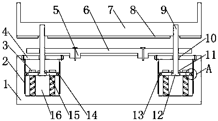
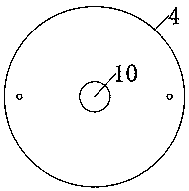
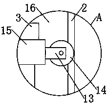
[0022] see Figure 1-3 , the present invention provides a technical solution: an electronic scale with an ore loading buffer structure, comprising a scale body 1, a weighing pan 7, a synchronous bar 6 and a buffer plate 15, the scale body 1 is located below the weighing pan 7, and the scale The upper surface of the left and right ends of the body 1 is provided with a buffer groove 16, the buffer groove 16 is a cylindrical tank body shape, and the buffer groove...


PUM


Abstract

The invention discloses an electronic scale with an ore loading buffering structure. The electronic scale comprises a scale body, a scale disc, synchronous rods and buffering plates. The scale body isarranged under the scale disc. Buffering grooves are arranged in upper surfaces of left and right ends of the scale body. Each buffering groove is in the shape of a cylindrical groove body. The buffering plates and buffering rods are arranged in the buffering grooves. Baffle plates are arranged around the upper surface of the scale disc and are capable of avoiding the phenomenon that a frameworkand ore fall together, so the safety is quite high and measurement is convenient to perform. The structure between the buffering grooves and the buffering plates is proper in design, and has good buffering effects. The synchronous rods are arranged on the buffering rods on left and right ends. Through the synchronous rods, synchronous raising and descending of the scale disc is ensured. A phenomenon that the scale disc inclines towards one side caused by uneven force is avoided. The ore is not liable to fall off, and the measurement is precise. The buffering structures are not likely to be damaged, and is quite long in service lifetime, convenient to disassemble and assemble and easy to independently change when parts of parts are damaged, so maintenance cost is reduced. The electronic scale is suitable for popularization.

Description

technical field [0001] The invention relates to the technical field of electronic scales, in particular to an electronic scale with an ore loading buffer structure. Background technique [0002] An electronic scale is a kind of weighing instrument, which is a tool for measuring the mass of an object by using Hooke's law or the principle of lever balance of force. According to the structural principles, it can be divided into three categories: mechanical scales, electronic scales, and electromechanical combination scales. The system (such as dial, electronic display instrument) is composed of 3 parts, and electronic scales are usually used to determine the quality of ore, but the electronic scale still has the following disadvantages in the process of actually using ore quality measurement: [0003] 1. The ore is often placed in a special frame and then transported to the surface of the electronic weighing pan for measurement, but the frame containing the ore is easy to slid...

Claims


Application Information

Patent Timeline
Patent Type & Authority Applications(China)
IPC IPC(8): G01G21/28
Inventor 王健靳能淼赖晓风
Owner QINGDAO HAIYIDA WEIGHING
Why Eureka
Try Eureka