Four-point bending fixture of thin plate for high stress loading and loading method thereof

A four-point bending, high-stress technology, applied in the direction of testing material strength, measuring devices, instruments, etc. by applying a stable bending force, can solve problems such as unstable sample holding, large application, and sample pop-up, and achieve structural Simple, avoid breaking, avoid falling off effect

Inactive Publication Date: 2018-01-19
武汉钢铁有限公司
4 Cites 6 Cited by

AI-Extracted Technical Summary

Problems solved by technology

[0004] At present, stress corrosion in my country is mainly concentrated in the fields of pipelines, containers and energy. The materials targeted are mainly hot-rolled plates and medium-thick plate materials, and their strength levels generally do not exceed 1000MPa, and the deflection impo...

Abstract

The invention discloses a four-point bending fixture of a thin plate for high stress loading and a loading method thereof. The fixture comprises a fixture body. The fixture body comprises a horizontalbottom plate, vertical side plates arranged on the two sides of the horizontal bottom plate and fixedly connected with the two sides of the horizontal bottom plate, and two top plates arranged at thetops of the vertical side plates on both sides and arranged to face each other; a horizontal bottom plate, two side vertical side plates and two top plates encloses a top-opened accommodating cavity,and the cross section of the accommodating cavity is in a rectangle shape; a loading block is arranged in the accommodating cavity and arranged in parallel with the horizontal bottom plate for carrying a thin plate sample, a loading force hole is arranged at the center of the bottom of the loading block, a loading screw is arranged at the center of the horizontal bottom plate, the top end of loading screw vertically penetrating through the horizontal bottom plate can be embedded in the loading force hole of the loading block to butt. The fixture of the invention can place the thin plate sample between the loading block and the two top plates, can effectively avoid problems of unstable loading of the thin plate sample or ejection of the sample and the like.

Application Domain

Material strength using steady bending forces

Technology Topic

Mechanical engineeringLoad force +1

Image

  • Four-point bending fixture of thin plate for high stress loading and loading method thereof

Examples

  • Experimental program(1)

Example Embodiment

[0031] The present invention will be further described in detail below in conjunction with the accompanying drawings and specific embodiments.
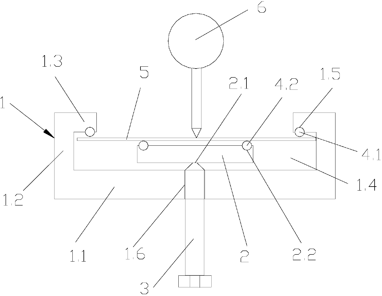
[0032] As shown in the figure, a four-point bending fixture for high-stress loading of thin plates includes a fixture body 1. The fixture body 1 includes a horizontal bottom plate 1.1, vertical side plates 1.2 arranged on both sides of the horizontal bottom plate 1.1 and vertically fixedly connected with it, and Two vertical side plates 1.2 on both sides are arranged at the top and oppositely arranged top plates 1.3; the horizontal bottom plate 1.1, the vertical side plates 1.2 on both sides, and the two top plates 1.3 enclose the accommodation chamber 1.4 with the top opening, and the accommodation chamber 1.4 has a rectangular cross-sectional shape. A loading block 2 arranged parallel to the horizontal bottom plate 1.1 in the accommodation chamber 1.4 is used to carry the thin plate sample 5. A loading force hole 2.1 is provided at the center of the bottom of the loading block 2; The threaded loading screw 3, the top of the loading screw 3 vertically penetrates the horizontal bottom plate 1.1, and can be embedded in the loading force hole 2.1 of the loading block 2 to abut against it;
[0033] The bottoms of the two top plates 1.3 are provided with a semicircular force positioning hole 1.5, and the two ends of the top of the loading block 2 are respectively provided with a semicircular loading positioning hole 2.2, and the force positioning hole 1.5 is provided with a first The ceramic rod 4.1 is provided with a second ceramic rod 4.2 in the loading positioning hole 2.2. The diameters of the two stress positioning holes 1.5 are both 5-6mm, and the distance between the center points of the two stress positioning holes 1.5 is 110-112mm. The diameters of the two loading positioning holes 2.2 are both 5-6 mm, and the distance between the center points of the two loading positioning holes 2.2 is 55-58 mm. The diameter of the first ceramic rod 4.1 and the second ceramic rod 4.2 is 5-6 mm, and the length is 15-18 mm. The thin-plate sample 5 is in the shape of a cuboid, and the length of the thin-plate sample 5 is 124-128 mm, the width is 10-15 mm, and the thickness is 0.8-2.5 mm. A threaded through hole 1.6 for installing the loading screw 3 is provided at the center of the horizontal bottom plate 1.1; the diameter of the threaded through hole 1.6 is 10-12 mm, the diameter of the loading screw 3 is 10-12 mm, and the length is 55-58 mm.
[0034] The present invention is used for the loading method of the four-point bending fixture of thin plate high stress loading, comprises the following steps:
[0035] 1) Place the thin plate sample 5 on the second ceramic rod 4.2 of the loading block 2, and adjust the position of the thin plate sample 5 so that it is located between the first ceramic rod 4.1 and the second ceramic rod 4.2;
[0036] 2) Tighten the loading screw 3 to apply an upward supporting force to the loading block 2 to ensure that the thin plate sample 5 is in a horizontal state;
[0037] 3) Fix the fixture body 1 clamping the thin plate sample 5 on the test bench, and then loosen the loading screw 3, so that the thin plate sample 5 is in a relaxed state;
[0038] 4) Use the thimble of the dial indicator 6 to touch the center of the thin plate sample 5, and adjust the dial indicator to zero;
[0039] 5) Calculate the deflection applied by the loading screw 3 according to the required loading stress, and then tighten the loading screw 3 to exert an upward support force on the loading block 2 until the required deflection is reached.
[0040] The above is only a specific embodiment of the present invention. It should be pointed out that any changes or substitutions that can be easily conceived by those skilled in the art within the technical scope disclosed in the present invention shall be covered by the protection scope of the present invention. within.

PUM

PropertyMeasurementUnit
Diameter5.0 ~ 6.0mm
Length15.0 ~ 18.0mm
Length124.0 ~ 128.0mm

Description & Claims & Application Information

We can also present the details of the Description, Claims and Application information to help users get a comprehensive understanding of the technical details of the patent, such as background art, summary of invention, brief description of drawings, description of embodiments, and other original content. On the other hand, users can also determine the specific scope of protection of the technology through the list of claims; as well as understand the changes in the life cycle of the technology with the presentation of the patent timeline. Login to view more.

Similar technology patents

Karst area soil nutrient reserve sampling and calculating method

Owner:INST OF SUBTROPICAL AGRI CHINESE ACAD OF SCI

Classification and recommendation of technical efficacy words

  • avoid breaking
  • reasonable design

Dyestripping mechanism and dyestripping method

Owner:AU OPTRONICS (XIAMEN) CORP +1

Diamond coating cutter, and preparation method and application thereof in high speed graphite processing

ActiveCN105563665AReduce cutting shock and vibrationavoid breaking
Owner:GUANGDONG UNIV OF TECH

Dual-channel gas state mercury exhaust gas sampling system

InactiveCN103149059Aavoid breakingImproving the measurement accuracy of front temperature
Owner:TIANJIN ENVIRONMENT MONITORING CENT

Embedding accuracy control construction method for embedded part of overlong equipment foundation platform

InactiveCN102134879Areasonable designSimple construction steps
Owner:SCEGC NO 6 CONSTR ENG GRP CO LTD

Frequency hopping communication anti-interference method based on cognitive radio

ActiveCN103441779AImprove anti-jamming communication abilityreasonable design
Owner:深圳市研谱科技有限公司
Why Eureka
Try Eureka