Student card control method and device
A control method and technology for a control device, which are applied to services based on location information, recording/indicating event time, nan, etc., can solve problems such as power consumption and student card power consumption, and achieve the purpose of saving energy consumption and improving battery life. Effect
- Summary
- Abstract
- Description
- Claims
- Application Information
AI Technical Summary
Problems solved by technology
Method used
Image

Examples
Embodiment Construction
[0078] It should be understood that the specific embodiments described here are only used to explain the present invention, not to limit the present invention.
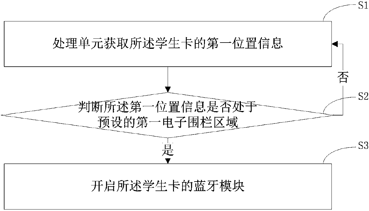
[0079] refer to figure 1 , the embodiment of the present invention provides a kind of student card control method, comprising steps:
[0080] S1. The processing unit acquires the first location information of the student card.
[0081] In this step, the above-mentioned processing unit is the data processing center and control center of the student card, such as electronic equipment such as a single-chip microcomputer. The above-mentioned first location information refers to the geographic location information of the student card. There are many ways to obtain the first location information, for example, to obtain the first location information by GPS, to obtain the first location information by base station positioning, and so on.
[0082] S2. Determine whether the first location information is in a preset first el...
PUM
 Abstract
Description
Claims
Application Information
 - Generate Ideas
- Intellectual Property
- Life Sciences
- Materials
- Tech Scout
- Unparalleled Data Quality
- Higher Quality Content
- 60% Fewer Hallucinations
Browse by: Latest US Patents, China's latest patents, Technical Efficacy Thesaurus, Application Domain, Technology Topic, Popular Technical Reports.
© 2025 PatSnap. All rights reserved.Legal|Privacy policy|Modern Slavery Act Transparency Statement|Sitemap|About US| Contact US: help@patsnap.com