Dust remover used in shoes processing workshops

A technology for processing workshops and dust removal devices, applied in applications, vacuum cleaners, household appliances, etc., can solve the problems of dust removal device blockage, foot injury, dust and waste, etc., and achieve the effect of practical function, reasonable structure and avoiding blockage

Inactive Publication Date: 2018-01-23
庄逸晖
View PDF4 Cites 5 Cited by
  • Summary
  • Abstract
  • Description
  • Claims
  • Application Information

AI Technical Summary

Problems solved by technology

[0002] The original intention of the invention of shoes is that walking barefoot on the ground will hurt the feet due to sharp objects on the ground. However, with the development of the times, the role of shoes has long been not limited to this, and comfort and fashion have become more important. Pursuing the goal, let nature take its course, people's demand for shoes will naturally increase, but we all know that during the production and processing of shoes, more dust and waste will be generated, and it is too troublesome to clean them up solely by manpower. Therefore, it is very necessary to study a dust removal device for a footwear processing workshop.
[0003] The existing dust removal devices for footwear processing workshops on the market are often simple dust collection devices, which can only clean up the dust on the ground, but are helpless for dust on footwear processing equipment or other higher positions. In addition, footwear The dust in the processing plant often contains a lot of waste materials. If the dust removal device is not cleaned in time during the long-term use process, it will easily cause the blockage of the dust removal device, which will affect the normal operation of the dust removal work.

Method used


Image

  • Dust remover used in shoes processing workshops
  • Dust remover used in shoes processing workshops
  • Dust remover used in shoes processing workshops

Examples


Embodiment Construction

[0017] The following will clearly and completely describe the technical solutions in the embodiments of the present invention with reference to the accompanying drawings in the embodiments of the present invention. Obviously, the described embodiments are only some, not all, embodiments of the present invention. Based on the embodiments of the present invention, all other embodiments obtained by persons of ordinary skill in the art without making creative efforts belong to the protection scope of the present invention.

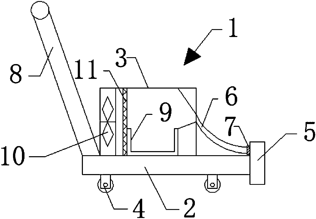
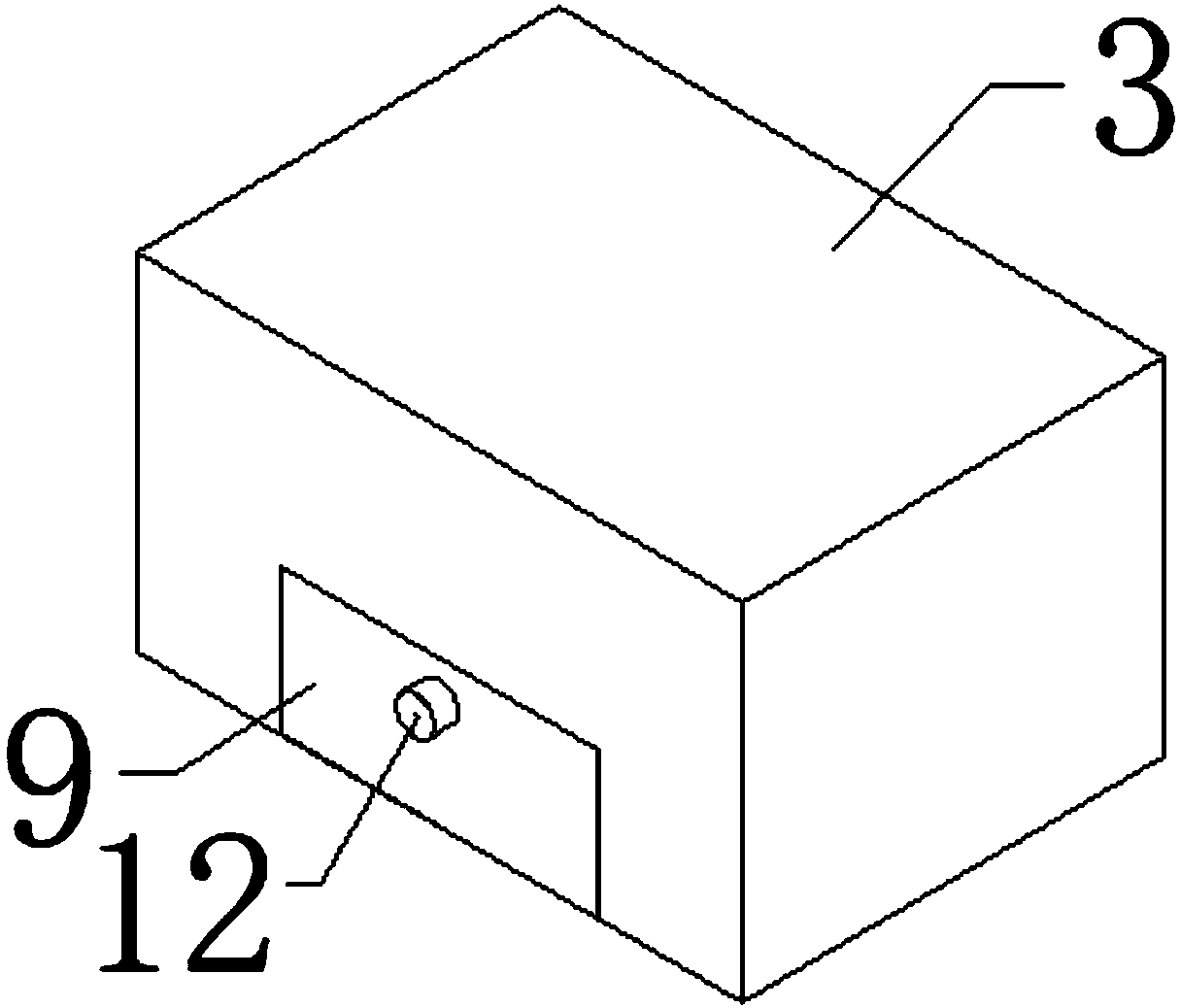
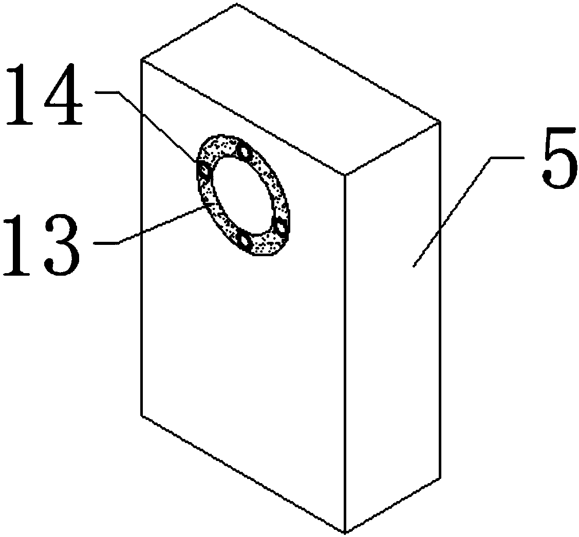
[0018] see figure 1 , figure 1 It is a structural schematic diagram of the present invention; a dust removal device for a shoe processing workshop, including a device body 1, and the device body 1 includes a base 2, a housing 3, a dust suction port 5, a connecting hose 6 and a two-way dust removal fan 10 , the housing 3 is fixedly mounted on the upper surface of the base 2, the lower surface of the base 2 is fixedly equipped with a roller 4, the device body 1...


PUM


Abstract

The invention discloses a dust remover used in shoes processing workshops, including a body. The body includes a base, a shell, a dust inlet, a connecting hose and a two-way dust extraction fan. The shell is fixedly installed on the upper surface of the base. A contact roller is installed on the lower surface of the base. The dust inlet is fixedly connected with the edge of the base. One end of the connecting hose is fixedly connected with the shell. Another end of the connecting hose is fixedly connected with the dust inlet. The junction between the dust inlet and the connecting hose is provided with a connecting tube. The edge of one end of the base, which is far from the dust inlet, is fixedly connected with a handle. A dust collecting box is installed inside the shell. The two-way dustextraction fan is fixedly installed on the inner wall of the shell. An air filter is fixedly installed between the dust collecting box and the two-way dust extraction fan. The dust remover used in shoes processing workshop is reasonable in structure and is practical in functions. Compared with the existed design in present markets, many improvements are applied on the dust remover used in shoes processing workshop. Therefore, the dust remover used in shoes processing workshop deserves to be expanded and applied.

Description

technical field [0001] The invention belongs to the technical field of dust removal devices, and in particular relates to a dust removal device for a shoe processing workshop. Background technique [0002] The original intention of the invention of shoes is that walking barefoot on the ground will hurt the feet due to sharp objects on the ground. However, with the development of the times, the role of shoes has long been not limited to this, and comfort and fashion have become more important. Pursuing the goal, let nature take its course, people's demand for shoes will naturally increase, but we all know that during the production and processing of shoes, more dust and waste will be generated, and it is too troublesome to clean them up solely by manpower. Therefore, it is very necessary to study a kind of dust removal device for a footwear processing workshop. [0003] The existing dust removal devices for footwear processing workshops on the market are often simple dust co...

Claims


Application Information

Patent Timeline
Patent Type & Authority Applications(China)
IPC IPC(8): A47L5/22A47L7/00A47L9/32
Inventor 庄逸晖
Owner 庄逸晖
Why Eureka
Try Eureka