
An orthopedic locking combination plate for medial acetabular approach

A steel plate and acetabular technology, which is applied in the field of orthopedic medial acetabular approach locking combined steel plate, can solve the problems of difficult installation of medical steel plate, selection change and fixation of the fixed plate, and achieve the effect of easy control

Inactive Publication Date: 2021-04-06
茂名市人民医院
View PDF5 Cites 0 Cited by
  • Summary
  • Abstract
  • Description
  • Claims
  • Application Information

AI Technical Summary

Problems solved by technology

[0002] The hip bone is composed of three parts: the ilium, the ischium, and the pubic bone. There is a large and deep socket called the acetabulum on the outer surface, which forms the hip joint with the femoral head. If the medical plate is installed on the upper bone surface of the iliopubic line of the pelvis, it will be difficult to touch the fracture site of the quadrilateral body on the medial side of the acetabulum, and it is impossible to shatter the fracture site. For effective fixation of bone fragments, an orthopedic medial acetabular approach locking composite plate is needed. For example, the patent application publication number 201620998861.8 discloses a kind of orthopedic medial acetabular approach locking composite plate. One end of the auxiliary fixation plate is The connecting part has a positioning part at the other end, and the locking steel plate has at least one connecting hole for fixing the auxiliary fixing steel plate. However, during the use of the above patents, the fixed length of the steel plate cannot be adjusted according to the needs, and the fixed steel plate cannot be selected and changed according to the actual situation.

Method used


Image

  • An orthopedic locking combination plate for medial acetabular approach
  • An orthopedic locking combination plate for medial acetabular approach
  • An orthopedic locking combination plate for medial acetabular approach

Examples


Embodiment Construction

[0022] The following will clearly and completely describe the technical solutions in the embodiments of the present invention with reference to the accompanying drawings in the embodiments of the present invention. Obviously, the described embodiments are only some, not all, embodiments of the present invention. Based on the embodiments of the present invention, all other embodiments obtained by persons of ordinary skill in the art without making creative efforts belong to the protection scope of the present invention.

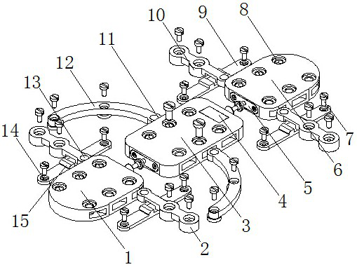
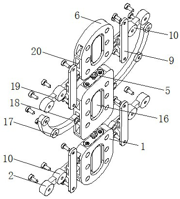
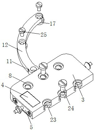
[0023] see Figure 1-5 , the present invention provides a technical solution: an acetabular medial approach locking combined plate for orthopedics, including a left plate 1, a middle plate 3 and a right plate 6, one side of the middle plate 3 is connected to the left plate through a connector 5 The steel plate 1 is connected, the other side of the middle steel plate 3 is connected with the right steel plate 6 through the connector 5, the upper side of the midd...


PUM


Abstract

The invention discloses an acetabular medial approach locking combined steel plate for orthopedics, which comprises a left steel plate, a middle steel plate and a right steel plate, one side of the middle steel plate is connected with the left steel plate through a connector, and the middle steel plate The other side is connected to the right steel plate through a connector, and first set screws are provided at the inner middle positions of the first screw holes, and the first set screws are connected to the outer bone body through the first screw holes. Both sides of the left steel plate and the right steel plate are equipped with more than six groups of rectangular through grooves distributed symmetrically at equal distances. By changing the number of middle steel plates connected between the left steel plate and the right steel plate, the steel plates can be fixed as required. The length is regulated, the selective connection of the horizontal steel strip and the curved steel strip can be selected and changed according to the actual situation, and the ultrasonic detector can control the actual situation of the bone body in real time, which is convenient for medical staff to control.

Description

technical field [0001] The invention relates to the technical field of medical devices, in particular to an acetabular medial approach locking combined steel plate for orthopedics. Background technique [0002] The hip bone is composed of three parts: the ilium, the ischium, and the pubic bone. There is a large and deep socket called the acetabulum on the outer surface, which forms the hip joint with the femoral head. If the medical plate is installed on the upper bone surface of the iliopubic line of the pelvis, it will be difficult to touch the fracture site of the quadrilateral body on the medial side of the acetabulum, and it is impossible to shatter the fracture site. For effective fixation of bone fragments, an orthopedic medial acetabular approach locking composite plate is needed. For example, the patent application publication number 201620998861.8 discloses a kind of orthopedic medial acetabular approach locking composite plate. One end of the auxiliary fixation pl...

Claims


Application Information

Patent Timeline
Patent Type & Authority Patents(China)
IPC IPC(8): A61B17/80
Inventor 徐海乔林世磅李永伟
Owner 茂名市人民医院
Learn More