Automatic locking mechanical arm

An automatic locking and mechanical arm technology, applied in the direction of manipulators, conveyor objects, chucks, etc., can solve problems such as object falling off, industrial construction troubles, clamping mechanism is not firm, etc., to achieve the effect of simple structure and improved safety and reliability

Active Publication Date: 2018-01-23
LIUZHOU FUNENG ROBOT DEV CO LTD
View PDF7 Cites 10 Cited by
  • Summary
  • Abstract
  • Description
  • Claims
  • Application Information

AI Technical Summary

Problems solved by technology

[0003] The existing mechanical arm needs to continuously provide power to keep the claw body in the clamping state during the whole process from grabbing the object to completely putting the object down. Once the equipment has a circuit or other failure, the claw body will lose its clamping state, resulting in The grasped object falls off, which leads to t

Method used


Image

  • Automatic locking mechanical arm
  • Automatic locking mechanical arm
  • Automatic locking mechanical arm

Examples


Example Embodiment

[0034] The present invention will be further described in detail below with reference to the accompanying drawings and embodiments, so that those skilled in the art can implement it with reference to the text of the description.

[0035] It should be understood that terms such as "having", "including" and "including" used herein do not equate the presence or addition of one or more other elements or combinations thereof.

[0036] In the description of the present invention, the terms "horizontal", "vertical", "upper", "lower", "front", "rear", "left", "right", "vertical", "horizontal", " The orientation or positional relationship indicated by "top", "bottom", "inner", "outer", etc. are based on the orientation or positional relationship shown in the drawings, and are only for the convenience of describing the present invention and simplifying the description, and are not indicative or implied. The device or element referred to must have a specific orientation, be constructed and op...


PUM


Abstract

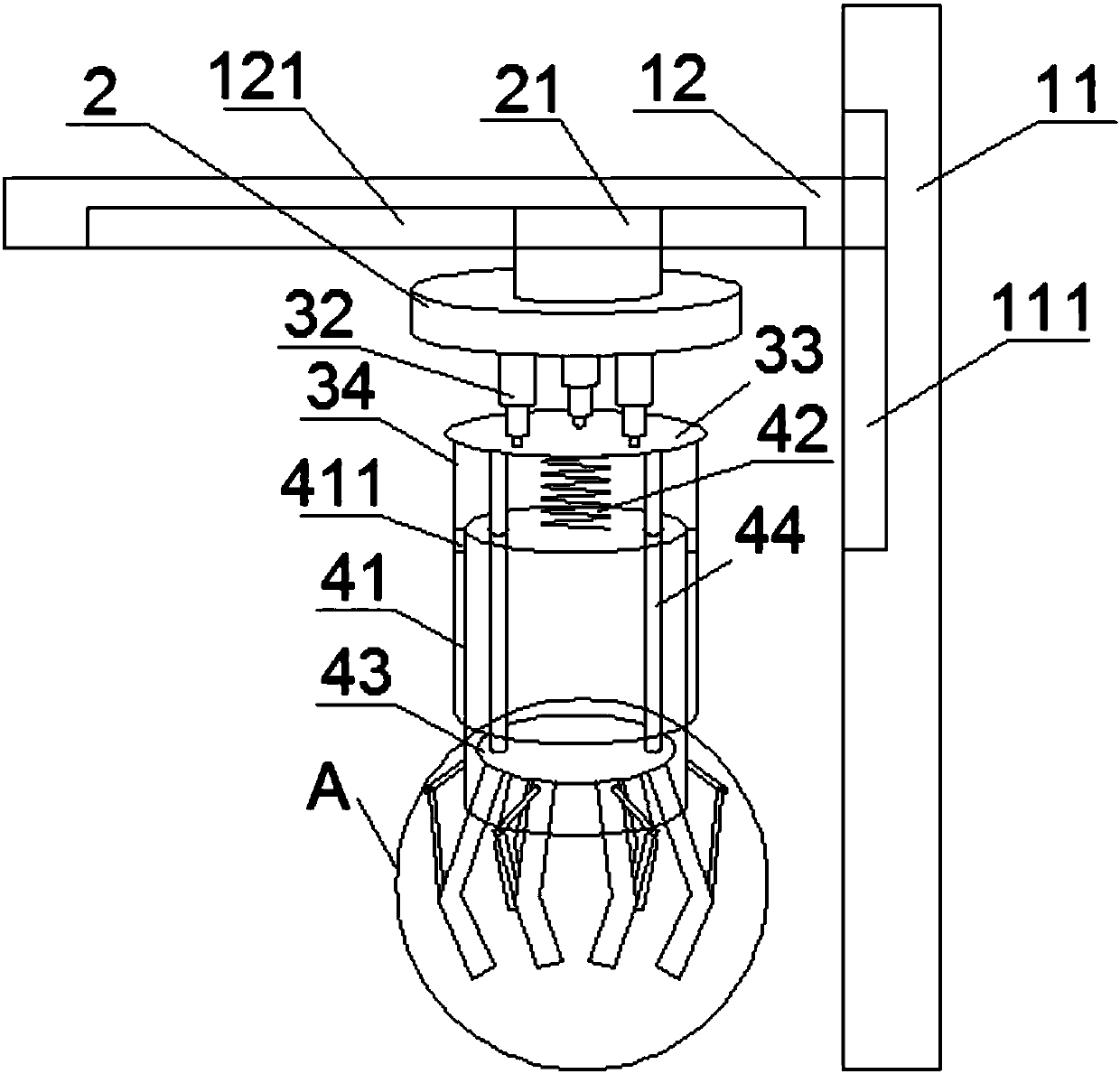
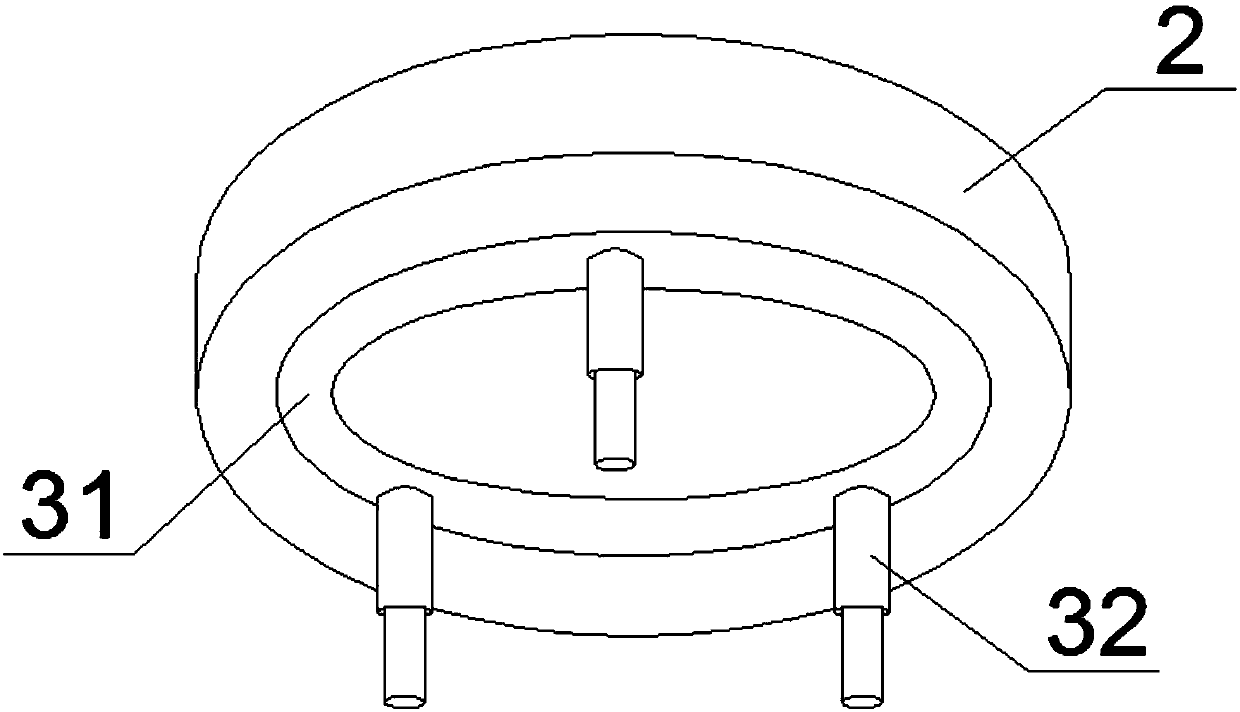
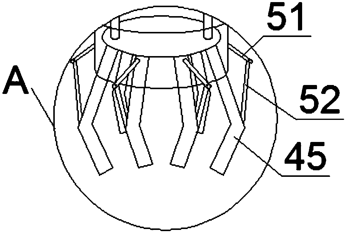
The invention discloses an automatic locking mechanical arm. The automatic locking mechanical arm comprises a rack, a rotating mechanism and a locking mechanism, wherein the rotating mechanism comprises a base which is in sliding connection with the rack, an annular rotating base which is in bearing connection with the base, three telescopic rods which are in fixed connection with the annular rotating base, a first disk which is hinged to the lower ends of the three telescopic rods, a second disk and stand columns; and the locking mechanism comprises a sleeve which is fixedly arranged on the lower surface of the first disk, a cylinder which is sleeved by the sleeve in a sliding manner and connection pieces. According to the automatic locking mechanical arm, due to the fact that compressionsprings are designed between the first disk and the cylinder, the cylinder automatically locks grasping of claws under the elastic force action of the compression springs, and safety and reliabilityof the automatic locking mechanical arm are improved; and by adjusting the different lengths of the three telescopic rods, the first disk is driven to incline at all angles and in all directions, andtherefore the claws are driven to rotate at multiple angles, and completion of grasping operation of objects to be grasped on multiple planes and in all directions is achieved.

Description

technical field [0001] The invention relates to the field of mechanical technology. More specifically, the present invention relates to a self-locking robotic arm. Background technique [0002] The mechanical arm can imitate certain movement functions of the human hand and arm, and is used to grab, carry objects or operate tools according to a fixed program; To protect personal safety, it is widely used in machinery manufacturing, metallurgy, electronics, light industry and other departments. [0003] The existing mechanical arm needs to continuously provide power to keep the claw body in the clamping state during the whole process from grabbing the object to completely putting the object down. Once the equipment has a circuit or other failure, the claw body will lose its clamping state, resulting in The grasped object falls off, which leads to the occurrence of safety accidents; the clamping mechanism between the claws of the mechanical arm is not firm, and when the heavy...

Claims


Application Information

Patent Timeline
IPC IPC(8): B65G47/91B25J15/06
Inventor 李应煌梁娟
Owner LIUZHOU FUNENG ROBOT DEV CO LTD
Why Eureka
Try Eureka