Optical current transformer-based grounding short circuit fault judgment method

A current transformer and grounding short-circuit technology, which is applied in the direction of instruments, measuring electricity, and measuring electrical variables, can solve the problems of protection misoperation, large differential balance adjustment coefficient, and large differences, so as to reduce intermediate links and measure range Wide, cost-effective effect

Inactive Publication Date: 2018-01-23
大唐观音岩水电开发有限公司 +1
View PDF6 Cites 1 Cited by
  • Summary
  • Abstract
  • Description
  • Claims
  • Application Information

AI Technical Summary

Problems solved by technology

There are several disadvantages in this scheme: First, according to the existing substation and power plant design regulations, the transformation ratio of the final configured three-phase electromagnetic CT and neutral point zero-sequence current CT may be very different, and the differential balance adjustment coefficient is too large. large, which affects the calculation accuracy of the differential current, thereby reducing the protection reliability; second, there is no effective criterion for the secondary circuit disconnection of the zero-sequence current transformer on the neutral point side; third, the two One side is zero-sequence current, one side is three-phase self-produced zero-sequence current, the other side is external zero-sequence current, and the CT transformation ratio and transmission characteristics are different, and the saturation speed and depth are also different when faults occur outside the zone, which is easy to cause protection Misuse

Method used


Image

  • Optical current transformer-based grounding short circuit fault judgment method

Examples


Embodiment Construction

[0030] The primary sensing optical fiber of the optical current transformer according to the present invention has two coiling modes. The technical solution of the optical current transformer based on one of the coiling modes will be described in detail below with reference to the accompanying drawings.

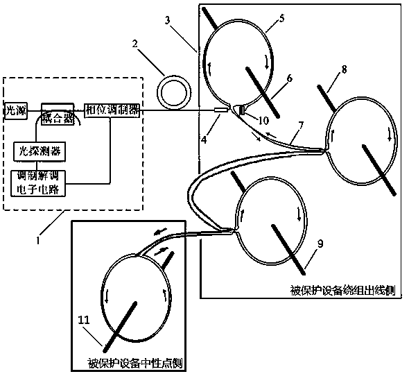
[0031] The structure of the optical current transformer is as figure 1 As shown, it includes an acquisition unit 1, a transmission optical cable 2 and a primary sensor 3 connected in sequence, wherein the acquisition unit 1 provides an optical signal for the system and calculates the primary current, and the acquisition unit 1 includes a light source, a coupler, a phase modulator, Optical detector and modulation and demodulation electronic circuit, the light source is used to generate the optical signal that meets the requirements; the coupler transmits the optical signal generated by the aforementioned light source to the phase modulator, and returns it from the primary senso...


PUM


Abstract

The invention discloses an optical current transformer-based grounding short circuit fault judgment method. According to the method, an all-fiber optical current transformer is used to directly measure the zero-sequence differential current of protected equipment; the primary sensing optical fiber of the all-fiber optical current transformer is made into a certain number of sensing optical fiber loops which are successively wound on primary conductors at two sides of the protected equipment; the sensing fiber loops can be distributed on three-phase conductors or star-connection neutral grounding conductors; each sensing fiber loop has the same number of turns and is completely closed; the sensing fiber loops mounted at the two sides of the protected equipment are wound to opposite directions respectively; and two optical fiber sensing paths which are equal in length and opposite in direction are arranged between any two adjacent sensing optical fiber loops in the whole optical fiber link are closely attached to each other in physical space. The optical current transformer directly outputs measured zero-sequence differential current; and when the zero-sequence differential current exceeds a limit, it is considered that a short-circuiting fault occurs in a primary system. The method has the advantages of low equipment cost, high reliability and high measurement accuracy.

Description

technical field [0001] The invention relates to a structure of an all-fiber optical current transformer, and also relates to a grounding short-circuit fault discrimination method based on the structure. Background technique [0002] Primary equipment such as main transformers, substation transformers, or factory transformers in power systems are prone to ground short-circuit faults. Zero-sequence overcurrent protection and zero-sequence differential protection are the two most common methods for identifying ground short-circuit faults. The zero-sequence overcurrent protection setting needs to cooperate with the protection settings at all levels, the setting is complicated, and the action time is long, especially for the final stage equipment. The setting delay is often too long, and it cannot be quickly moved to remove the fault. Zero-sequence differential protection has been widely used because of its faster action speed and good selectivity. At present, the composition of...

Claims


Application Information

Patent Timeline
Patent Type & Authority Applications(China)
IPC IPC(8): G01R31/02
Inventor 方善臣王凯邓涛王耀周方群王光罗苏南张琦雪须雷陈俊
Owner 大唐观音岩水电开发有限公司
Why Eureka
Try Eureka