Concrete strength testing device and using method thereof

A technology for concrete strength and testing equipment, which is applied in the direction of measuring equipment, strength characteristics, and testing material hardness, etc., and can solve the problems of single adjustable angle posture and limited functions of the rebound hammer

Pending Publication Date: 2021-01-29
江苏诚意智腾建材科技发展有限公司
View PDF1 Cites 3 Cited by
  • Summary
  • Abstract
  • Description
  • Claims
  • Application Information

AI Technical Summary

Problems solved by technology

The above-mentioned patent has the following disadvantages: the adjustable angle and posture of the rebound hammer are too single, and it needs the cooperation of concrete specimens, and its function is greatly limited in the concrete test link for building acceptance

Method used


Image

  • Concrete strength testing device and using method thereof
  • Concrete strength testing device and using method thereof
  • Concrete strength testing device and using method thereof

Examples


Embodiment 1

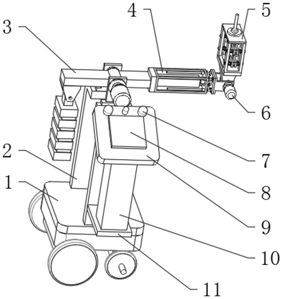
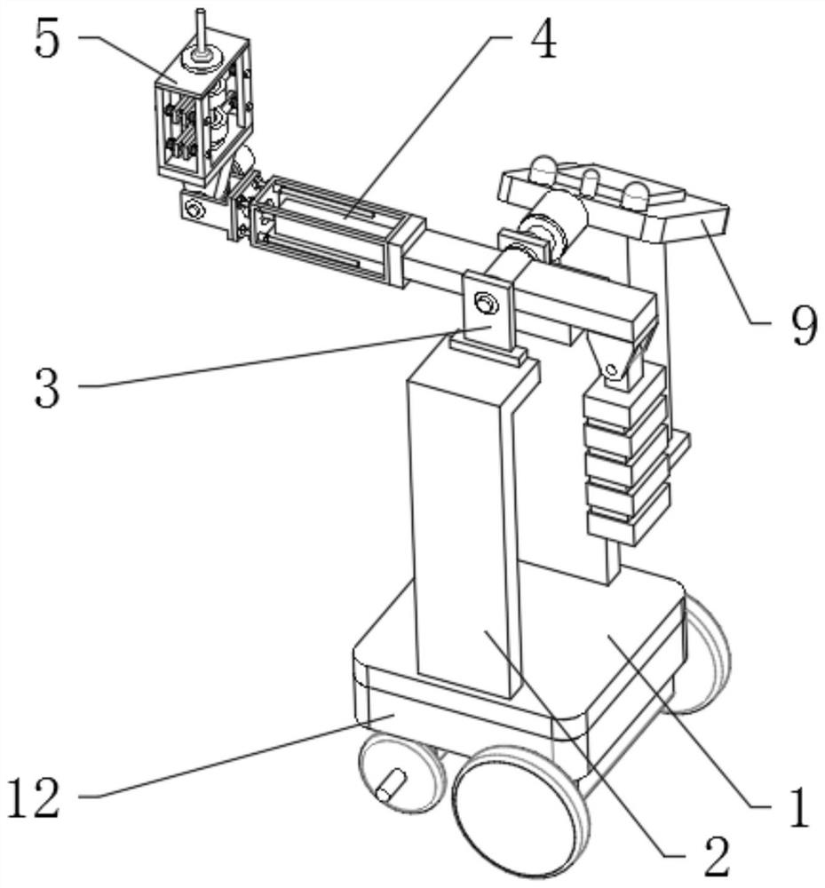
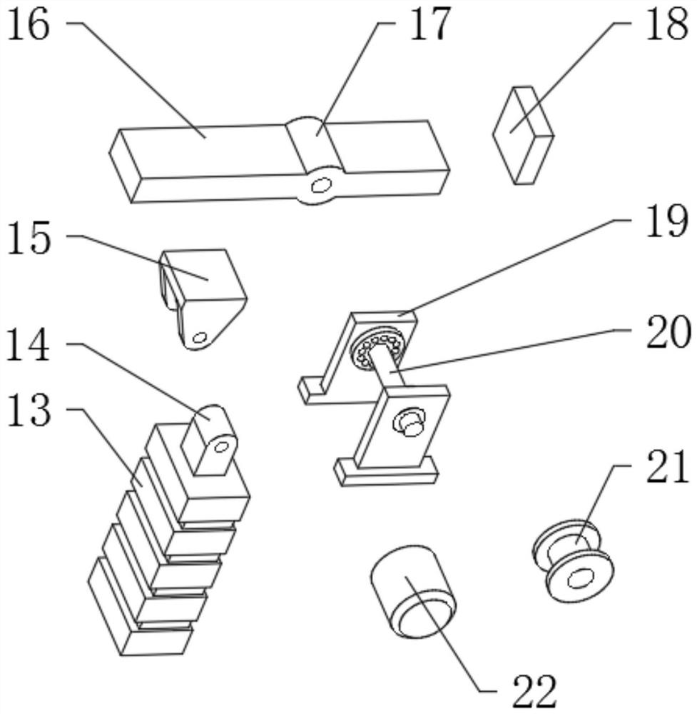
[0041] A concrete strength testing device, such as Figure 1-7 As shown, it includes a bottom plate 1, the top outer wall of the bottom plate 1 is fixedly connected with a stand 2, the number of stand 2 is two, the top outer wall of the stand 2 is fixedly connected with a main adjustment assembly 3, and the outer wall of one side of the main adjustment assembly 3 is fixed. Connected with a telescopic assembly 4, the outer wall of one side of the telescopic assembly 4 is fixedly connected with an auxiliary adjustment assembly 6, and the outer wall of one side of the auxiliary adjustment assembly 6 is fixedly connected with a placement assembly 5, and the interior of the placement assembly 5 is provided with a rebound instrument 34; the main adjustment assembly 3 includes a beam 16 and a bracket 19, the bottom outer wall of the bracket 19 is fixedly connected to the top outer wall of the stand 2, the inner wall of the beam 16 is provided with a middle cylinder 17, and the inner w...

Embodiment 2

[0048] A method for using a concrete strength testing device, such as Figure 1-7 As shown, the test device described in this embodiment is the test device in embodiment 1, and its method of use includes the following steps;

[0049] S1: install the rebound hammer 34; directly stretch the splint 40 through the rebound hammer 34, and fix the rebound hammer 34 by the splint 40, and the plug sleeve 32 can provide further fixation;

[0050] S2: driving device; through external command remote control, the body 12 drives the device into the measurement area;

[0051] S3: Wall measurement; the main adjustment component 3 is leveled, and the rebound instrument 34 is used for measurement. When the position needs to be changed, the main adjustment component 3 and the auxiliary adjustment component 6 realize the angle adjustment, and keep the placement component 5 always in the horizontal direction;

[0052] S4: Ceiling measurement; the main adjustment component 3 is vertical, and the r...


PUM


Abstract

The invention discloses a concrete strength testing device and a using method thereof, and relates to the technical field of concrete detection. The problem that an existing device cannot detect multiple positions is solved. The device comprises a bottom plate, two vertical frames are fixedly connected to the outer wall of the top of the bottom plate, a main adjusting assembly is fixedly connectedto the outer walls of the tops of the vertical frames, a telescopic assembly is fixedly connected to the outer wall of one side of the main adjusting assembly, an auxiliary adjusting assembly is fixedly connected to the outer wall of one side of the telescopic assembly, and a placement assembly is fixedly connected to the outer wall of one side of the auxiliary adjusting assembly; a rebound apparatus is arranged in the placement assembly; the using method of the device comprises the following steps: mounting the resiliometer, mounting the driving device, measuring the wall, measuring the ceiling, measuring the ground and returning and displaying the data. The placement assembly is responsible for assembling instruments, the manual labor load can be reduced, the placement assembly can be adjusted to be in various angle postures, and nondestructive testing can be directly carried out on site.

Description

technical field [0001] The invention relates to the technical field of concrete detection, in particular to a concrete strength testing device and a use method thereof. Background technique [0002] When conducting concrete testing, non-destructive testing methods are often preferred. The rebound hammer manufactured by using the rebound principle is very convenient. It can detect concrete on site, thereby avoiding the trouble of making concrete specimens, but the rebound hammer needs to be manually held. For the measurement of concrete in the same area, many points are required, and manual measurement is very inconvenient. [0003] After retrieval, the Chinese patent application number is 201910536835.1, which discloses a conductive concrete strength testing device, which relates to the technical field of conductive concrete strength testing; a power supply is installed on the upper left outer wall of the base, and a There is a support rod, the front end outer wall of the s...

Claims


Application Information

Patent Timeline
Patent Type & Authority Applications(China)
IPC IPC(8): G01N3/52G01N3/02
CPCG01N3/02G01N3/52G01N2203/0083G01N2203/0244
Inventor 周珂珂
Owner 江苏诚意智腾建材科技发展有限公司
Why Eureka
Try Eureka