
Automatic drilling device for magnetic suspension track panel induction plate

A drilling device and induction plate technology, applied in the field of maglev, can solve the problems of safety accidents, low operation efficiency, short operation window period and the like

Pending Publication Date: 2022-07-22
CHINA RAILWAY CONSTR HEAVY IND
View PDF0 Cites 0 Cited by
  • Summary
  • Abstract
  • Description
  • Claims
  • Application Information

AI Technical Summary

Problems solved by technology

[0004] Among them, the induction plate b and the rail row a are usually connected by means of mechanical screw connection, pin connection and adhesive bonding. Due to the large number of threaded holes, the amount of processing is large, which has become a constraint on the assembly efficiency of the rail row. one of the main factors of
At the same time, after the maglev line is put into operation, due to factors such as vibration or screw falling off, part of the induction plate b cannot cling to the upper surface of the rail row a, which is likely to cause safety accidents. Therefore, it is necessary to periodically check the rail row a sex maintenance
[0005] At present, the replacement and drilling of induction plate b are usually carried out manually, which not only has low operating efficiency and high labor intensity, but also has disadvantages such as inconvenient operation on the line, harsh environment, short operating window period, and high risk factor.
At the same time, in the assembly process, in the prior art, manual scribing and ordinary drilling machines are generally used to drill the induction plate, and about 90 hole positions need to be processed in a single 12m rail row, resulting in low processing efficiency and labor costs in the existing mode. High strength, poor processing quality, unable to meet the needs of large-scale rail row processing
In addition, when the induction plate b is manually drilled with a drilling rig or a drilling machine, it is usually affected by the cutting reaction force during drilling, resulting in a decrease in drilling accuracy and a deviation in the drilling position

Method used


Image

  • Automatic drilling device for magnetic suspension track panel induction plate
  • Automatic drilling device for magnetic suspension track panel induction plate
  • Automatic drilling device for magnetic suspension track panel induction plate

Examples


Embodiment Construction

[0032] The technical solutions in the embodiments of the present invention will be clearly and completely described below with reference to the accompanying drawings in the embodiments of the present invention. Obviously, the described embodiments are only a part of the embodiments of the present invention, but not all of the embodiments. Based on the embodiments of the present invention, all other embodiments obtained by those of ordinary skill in the art without creative efforts shall fall within the protection scope of the present invention.

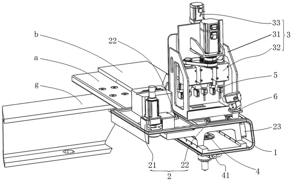
[0033] Please refer to figure 2 , figure 2 It is a schematic diagram of the overall structure of a specific embodiment provided by the present invention.

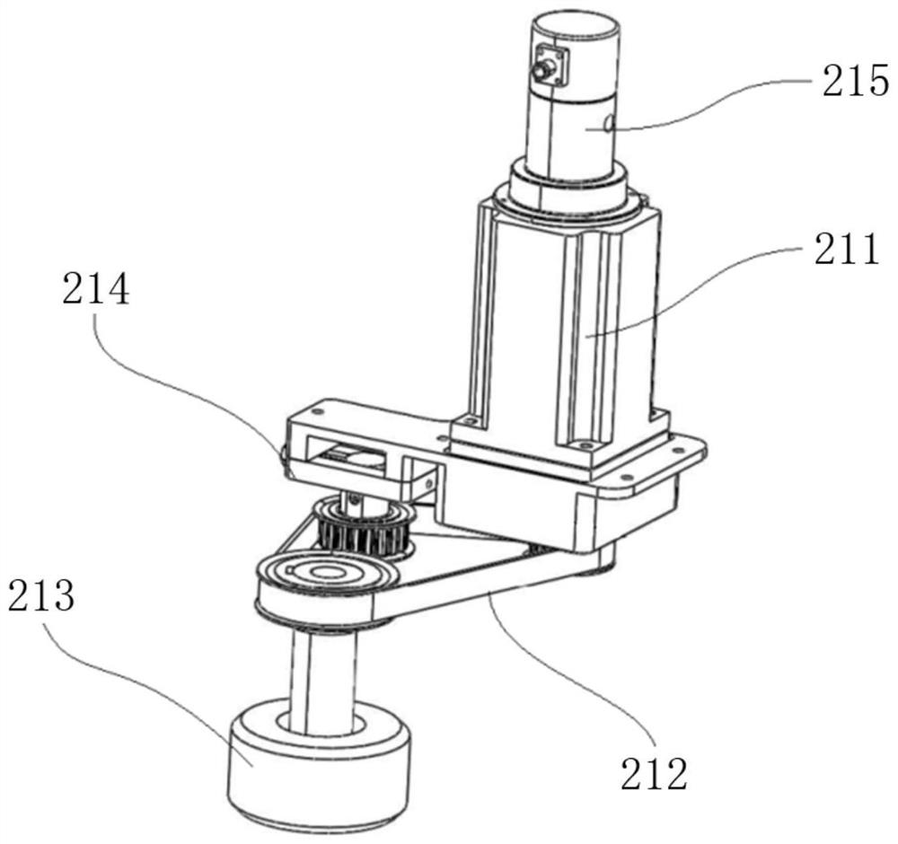
[0034] In a specific embodiment provided by the present invention, the automatic drilling device for magnetic suspension rail row induction plates mainly includes a vehicle frame 1 , a traveling mechanism 2 , a drilling mechanism 3 and a clamping mechanism 4 .

[0035] Wherein,...


PUM


Abstract

The invention discloses a magnetic suspension track panel induction plate automatic drilling device which comprises a frame arranged on a track panel in a sleeving mode in the width direction, a walking mechanism arranged on the frame and used for walking in the extending direction of the track panel, and a drilling mechanism arranged on the surface of the frame and used for drilling an induction plate of the track panel. And the clamping mechanism is vertically arranged on the bottom surface of the frame in a telescopic manner and is used for propping against the detection surface of the track panel when the drilling mechanism is used for drilling. Thus, the position of the frame in the extending direction of the track panel is sequentially adjusted through walking of the walking mechanism on the track panel, the sensing plate is drilled through the drilling mechanism every time after the position is adjusted in place, meanwhile, the clamping mechanism abuts against the detection face of the track panel in the drilling period, the frame and the sensing plate are fastened, deviation of drilling operation is prevented, and the drilling efficiency is improved. According to the drilling device, drilling operation of the induction plate on the track panel can be conveniently and efficiently achieved, the drilling operation efficiency and the drilling operation quality are improved, and the manual labor load is reduced.

Description

technical field [0001] The invention relates to the technical field of magnetic suspension, in particular to an automatic drilling device for magnetic suspension rail row induction plates. Background technique [0002] Medium and low speed maglev is a new type of urban rail transit technology with independent intellectual property rights in my country. It has the advantages of strong climbing ability, small turning radius, high safety, and low noise. It is suitable for large and medium-sized cities with complex terrain and crowded buildings, tourism Scenic spots, etc. [0003] Rail platoons are the core and key components of medium and low-speed maglev traffic, such as figure 1 As shown, the rail row as a whole is F-shaped, commonly referred to as "F rail". The rail row a mainly includes an induction plate b arranged on its upper surface, a wing plate surface d arranged on its inner side, an inner side surface f perpendicular to the wing plate surface d, a braking surface e...

Claims


Application Information

Patent Timeline
Patent Type & Authority Applications(China)
IPC IPC(8): B23B41/00B23B39/14B23Q1/01
CPCB23B41/00B23B39/14B23Q1/015
Inventor 覃南兴张建党王幸福孟献源胡建其崔静
Owner CHINA RAILWAY CONSTR HEAVY IND
Learn More