
Wire threading machine

A wire threading and wire machine technology, applied in the field of wire threading machines, can solve the problems that steel strands cannot be reused, affect the turnover speed of templates, increase the use of steel strands, etc., achieve reduction of manual labor load, low manufacturing cost, The effect of reducing working hours

Inactive Publication Date: 2015-06-03
CHINA RAILWAY SHISIJU GROUP CORP
View PDF0 Cites 0 Cited by
  • Summary
  • Abstract
  • Description
  • Claims
  • Application Information

AI Technical Summary

Problems solved by technology

[0002] When the box girder is prefabricated, the threading process of the prestressed steel strand is manual wire feeding, that is, the steel strand is cut into the required length and then manually threaded. The wire threading time is long, and the beam body cannot be pre-tensioned immediately. Pull, to a certain extent, affects the turnover speed of the template
The length of the truncated steel strand depends on the length of the pipe of the box girder. In order to speed up the wire threading speed, generally only two lengths of steel strand are cut off, and the steel strand outside the pipe is cut off after the wire threading is completed, thus increasing The consumption of steel strands is reduced, and the truncated steel strands cannot be reused, resulting in waste

Method used


Image

  • Wire threading machine
  • Wire threading machine
  • Wire threading machine

Examples


Embodiment Construction

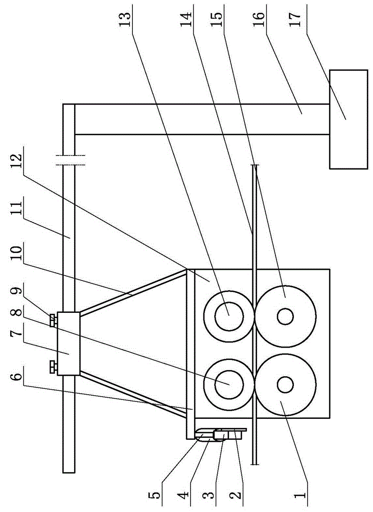
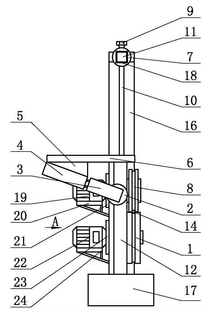
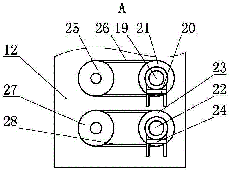
[0009] threading machine, such as figure 1 and figure 2 As shown, it includes a base 17, a vertical bar 16 is installed on the base 17, a horizontal shaft 11 is installed on the top of the vertical bar 16, a fixed seat 6 is hoisted on the horizontal shaft 11, a fixed plate 12 is installed on the bottom of the fixed seat 6, and a driving wheel is installed on the fixed plate 12 8 and lower driving wheel 1, steel strand 14 is set between upper driving wheel 8 and lower driving wheel 1, and steel strand 14 is all tangent to upper driving wheel 8 and lower driving wheel 1, and the axle of upper driving wheel 8 is connected Motor 19, the wheel shaft of lower driving wheel 1 connects lower motor 22, upper motor fixing mount 20 and lower motor fixing mount 24 are set on the fixed plate 12, upper motor 19 and lower motor 22 are respectively installed in upper motor fixing mount 20 and lower motor fixing On the frame 24, the cylinder 4 is installed on the fixed seat 6, the cylinder 4...


PUM


Abstract

The invention provides a wire threading machine. The wire threading machine comprises a base; a vertical rod is mounted on the base; a cross shaft is mounted at the top of the vertical rod; a holder is hanged on the cross shaft; a fixed plate is mounted on the lower part of the holder; an upper driving wheel and a lower driving wheel are mounted on the fixed plate; a steel strand is arranged between the upper driving wheel and the lower driving wheel; the wheel shaft of the upper driving wheel is connected with an upper motor, while the wheel shaft of the lower driving wheel is connected with a lower motor; a cylinder is mounted on the holder; a cutter is mounted on the piston shaft of the cylinder. The steel strand is threaded into the pipeline of a box beam by use of the wire threading machine, and is cut off according to the length of the pipeline. The wire threading machine is capable of effectively reducing the labor load, reducing the working time, and improving the working efficiency and the threading quality; the steel strands different in length can be threaded according to different requirements, the usage amount of the steel strands is reduced, the step of secondarily cutting off the steel strands is avoided, the operation is convenient and simple, the waste of the steel strands is reduced and the production cost is saved. The wire threading machine also has the advantages of simple and compact structure, low manufacturing cost and simple and convenient use.

Description

technical field [0001] The invention relates to a wire threading machine. Background technique [0002] When the box girder is prefabricated, the threading process of the prestressed steel strand is manual wire feeding, that is, the steel strand is cut into the required length and then manually threaded. The wire threading time is long, and the beam body cannot be pre-tensioned immediately. Pulling, to a certain extent, affects the turnover speed of the template. The length of the truncated steel strand depends on the length of the pipe of the box girder. In order to speed up the wire threading speed, generally only two lengths of steel strand are cut off, and the steel strand outside the pipe is cut off after the wire threading is completed, thus increasing The consumption of steel strand is reduced, and the truncated steel strand cannot be reused, resulting in waste. Contents of the invention [0003] In order to solve the above problems, the object of the present inve...

Claims


Application Information

Patent Timeline
IPC IPC(8): B21F11/00
CPCB21F11/00
Inventor 许江鹏王东王利
Owner CHINA RAILWAY SHISIJU GROUP CORP
Learn More