
Anisotropic high-strength wear-resisting repair material sample manufacturing mold

A high-strength, repairing material technology, applied in the preparation of test samples, manufacturing tools, ceramic molding machines, etc., can solve the problems of detection failure, broken, easy to fall off, etc., to achieve consistency, simple structure, easy disassembly and The effect of assembly

Pending Publication Date: 2018-01-26
YIXING GUOQIANG FURNACE IND
View PDF3 Cites 0 Cited by
  • Summary
  • Abstract
  • Description
  • Claims
  • Application Information

AI Technical Summary

Problems solved by technology

This method is prone to irregular fracture and fragmentation of the sample incision in the process of sample preparation, and it is difficult to obtain a complete standard sample, resulting in the inability to accurately perform material performance testing.
[0003] Furthermore, when testing the tensile strength of the sample, the general square sample is easy to fall off during the clamping process, resulting in the failure of the test, which needs to be improved

Method used


Image

  • Anisotropic high-strength wear-resisting repair material sample manufacturing mold
  • Anisotropic high-strength wear-resisting repair material sample manufacturing mold

Examples


Embodiment 1

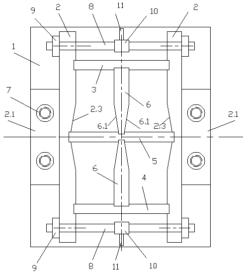
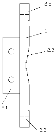
[0013] Example 1: A mold for making a sample of a heterosexual high-strength wear-resistant repair material, including a bottom plate 1, two symmetrical side plates 2 arranged on the bottom plate 1, and upper and lower horizontal plates arranged between the two side plates 2 ( 3, 4) and the horizontal partition 5 parallel to the upper and lower horizontal plates (3, 4) and located on the center line of the side plate 2, the center of the upper and lower horizontal plates (3, 4) and the horizontal partition 5 are provided with a vertical partition 6, the bottom plate 1. Side panels 2, upper and lower horizontal panels (3, 4), horizontal partitions 5 and vertical partitions 6 constitute four mold cavities, and the outer sides of the two side panels 2 are fixedly connected with connecting lugs 2.1. The sheet 2.1 is provided with connecting through holes, and the corresponding connecting through holes on the bottom plate 1 are provided with connecting holes, and the two are fixedly...


PUM


Abstract

An anisotropic high-strength wear-resisting repair material sample manufacturing mold comprises a bottom plate, two symmetric side plates arranged on the bottom plate, an upper transverse plate, a lower transverse plate and a transverse partition plate, wherein the upper transverse plate and the lower transverse plate are arranged between the two side plates, and the transverse partition plate isparallel to the upper transverse plate and the lower transverse plate and is located on the center lines of the side plates. Vertical partition plates are arranged in the centers of the upper transverse plate, the lower transverse plate and the transverse partition plate. Four mold cavities are formed by the bottom plate, the side plates, the upper transverse plate, the lower transverse plate, thetransverse partition plate and the vertical partition plates. Connecting lug pieces are fixedly connected to the outer sides of the two side plates and provided with connecting through holes. Connecting holes corresponding to the connecting through holes are formed in the bottom plate, and the connecting holes and the connecting through holes are in bolted fixed connection. Symmetric through holes are formed in the upper ends and the lower ends of the two side plates. Pull rods are arranged in the through holes. External threads are machined at the two ends of each pull rod. The two ends of the pull rods penetrate out of the outer sides of the two side plates and are provided with nuts for rotary connection and tightening. The structure is simple, the sample manufacturing precision is high, demounting is simple and convenient, and multiple samples can be manufactured through one plate.

Description

technical field [0001] The invention relates to the field of refractory material production, in particular to a mold for making a tensile testing sample of a refractory material. Background technique [0002] High-strength wear-resistant repair material is a refractory material made of unshaped refractory material mixed with refractory aggregate with a certain particle size distribution, powder, binder and admixture, also known as bulk refractory material. It is used to repair the furnace body. It can be used directly after self-hardening without firing. However, it must be made into a fixed sample to test its index and performance. Until now, the experiment of amorphous refractories Different research methods, lack of or no standards, even if there are standards, they are not uniform. There is also no uniform method and standard for the preparation of most unshaped refractory test samples, and there is no special mold for sample production. The performance testing of most...

Claims


Application Information

Patent Timeline
IPC IPC(8): B28B7/00G01N1/28
Inventor 林国强
Owner YIXING GUOQIANG FURNACE IND
Learn More