Composite material forming machine

A composite material and forming machine technology, applied in punching machines, presses, manufacturing tools, etc., can solve the problems of eccentric load of the slider and the inability of the press to meet the actual needs, so as to increase the pressing force, ensure the parallelism, and improve the response. effect of speed

Pending Publication Date: 2018-01-26
JDM JINGDA MASCH (NINGBO) CO LTD
View PDF0 Cites 3 Cited by
  • Summary
  • Abstract
  • Description
  • Claims
  • Application Information

AI Technical Summary

Problems solved by technology

[0003] Due to the variety of workpiece shapes processed by the composite material forming machine, the required processing conditions are also very different, and the slide block of the press often appears unbalanced load phenomenon, so it is necessary to solve the problem of speed and efficiency, and to be able to adjust flexibly to meet the Various workpieces and processing conditions, especially to meet the requirements of pressurizing the slider and eliminating the eccentric load of the slider, but the existing presses still cannot meet the actual needs

Method used


Image

  • Composite material forming machine
  • Composite material forming machine
  • Composite material forming machine

Examples


Embodiment Construction

[0024] The present invention will be further described below in conjunction with the embodiments of the accompanying drawings.

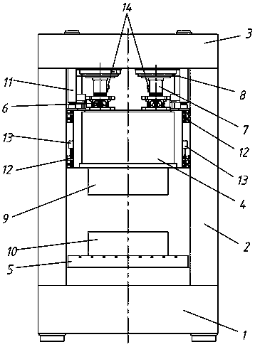
[0025] Such as figure 1 , figure 2 As shown, a composite material forming machine includes a base 1, a column 2, a top seat 3, a slider 4, a worktable 5, a brake mechanism 6, a pressurized cylinder 8, an upper mold 9, a lower mold 10, and a lifting cylinder 11 .

[0026] The frame of the composite material forming machine is formed between the top seat 3 and the base 1 through the support of the column 2 .

[0027] In the above-mentioned frame, the above-mentioned worktable 5 is installed on the base 1 , the lower mold 10 is installed on the worktable 5 , the upper mold 9 is arranged above the lower mold 10 , and the upper mold 9 is installed on the slide block 4 .

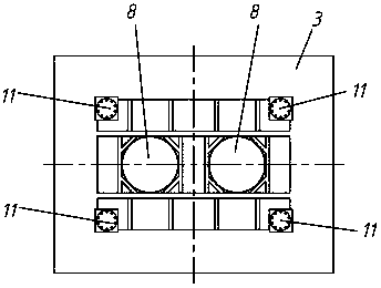
[0028] There are two above-mentioned pressurized oil cylinders 8, which are installed on the top seat 3. The two pressurized oil cylinders 8 are symmetrically arranged on both sides ...


PUM


Abstract

A composite material forming machine comprises a base, stand columns, a top base, a sliding block, a locking mechanism, pressurizing oil cylinders, an upper die, a lower die and lifting oil cylinders.A frame of the composite material forming machine is formed between the top base and the base through supporting of the stand columns. In the frame, the lower die is arranged on the base, the upper die is arranged above the lower die and arranged on the sliding block, the pressurizing oil cylinders are arranged on the top base, and the heads of piston rods of the pressurizing oil cylinders penetrate the sliding block. The locking mechanism is arranged on the sliding block, and the locking mechanism can lock or unlock the piston rods of the pressurizing oil cylinders. The lifting oil cylindersare arranged on the top base, and piston rods of the lifting oil cylinders are fixed to the four corners of the sliding block. A control system is further arranged to control the lifting oil cylinders, the locking mechanism and the pressurizing oil cylinders; when the sliding block rapidly ascends and descends, the lifting oil cylinders ascend and descend, and the locking mechanism unlocks the piston rods of the pressurizing oil cylinders; and when the sliding block is pressurized, the locking mechanism locks the piston rods of the pressurizing oil cylinders, the pressurizing oil cylinders pressurize the sliding block, and the lifting oil cylinders are used for conducting leveling on the sliding block.

Description

technical field [0001] The invention relates to a composite material forming machine. Background technique [0002] With the society's emphasis on environmental and energy issues, as well as the development of material technology and the expansion of applications, composite materials, as a class of advanced materials, are widely used in aerospace and new energy vehicles due to their high specific stiffness, specific strength and other characteristics. Fields with high quantitative requirements have broad application prospects, and composite material forming machines, as the main production equipment for composite material products, have also developed rapidly. [0003] Due to the variety of workpiece shapes processed by the composite material forming machine, the required processing conditions are also very different, and the slide block of the press often appears unbalanced load phenomenon, so it is necessary to solve the problem of speed and efficiency, and to be able to a...

Claims


Application Information

Patent Timeline
Patent Type & Authority Applications(China)
IPC IPC(8): B30B1/34B30B15/00B29C70/46
Inventor 郑良才许俊张明明殷莎
Owner JDM JINGDA MASCH (NINGBO) CO LTD
Why Eureka
Try Eureka