Adjustable unwinding device for cable production

A pay-off device and adjustable technology, applied in the direction of cable/conductor manufacturing, circuits, electrical components, etc., can solve the problems of affecting the operation of insulating jackets, reducing the number of cable finished products, and insufficient tension, so as to achieve good follow-up processing quality, Smooth follow-up processing, fast and easy adjustment

Active Publication Date: 2018-01-26
江西瑞金金字电线电缆有限公司
View PDF7 Cites 4 Cited by
  • Summary
  • Abstract
  • Description
  • Claims
  • Application Information

AI Technical Summary

Problems solved by technology

[0004] (1) The existing pay-off device only relies on the support wheel on one side of the pay-off wheel to make the cable have tension within a certain length. The distance between the pay-off wheel and the support wheel is defined as the cable suspension distance. The distance between the pay-off wheel and the support wheel of the cable device is fixed, and it is inconvenient to move the pay-off device and the pay-off wheel even if the distance is adjusted, and different types of cables do not necessarily have the same tension force for the same cable suspension distance, so When the cable tension is not enough, the cable may appear coiled, bent and other undesirable phenomena, which will affect the operation of the subsequent extruder to put the insulating jacket on the cable, so that the quality of the subsequent processing of the cable is not good enough, and the qualified length is greatly reduced;
[0005] (2) Existing pay-off devices and support wheels are generally fixed-distance support wheels on one side of the pay-off wheel generally without a pulley lifting device to change the tension of the cable, so that a pay-off device can only give a limited One or several types of cables are laid out, and for other types of cables, the subsequent processing of the cables will be lost due to insufficient tension or excessive tension, which greatly reduces the number of finished cables

Method used


Image

  • Adjustable unwinding device for cable production
  • Adjustable unwinding device for cable production
  • Adjustable unwinding device for cable production

Examples


Embodiment

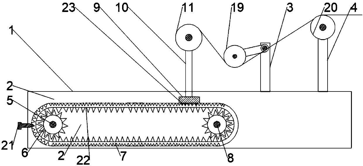
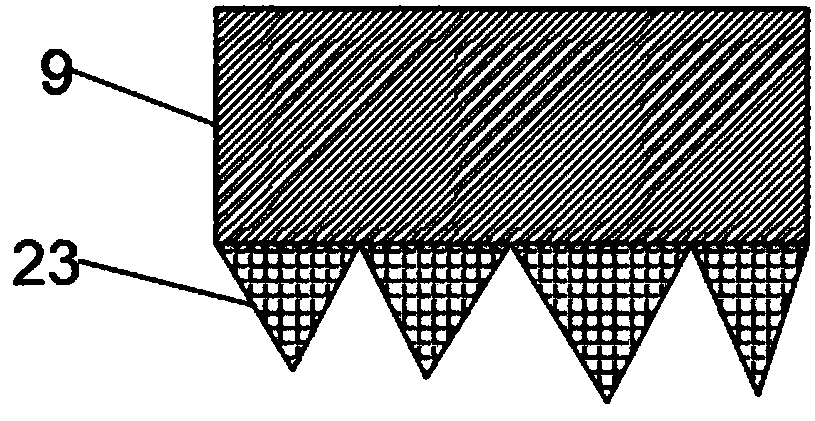
[0027] like figure 1 As shown, the present invention provides an adjustable pay-off device for cable production, including a base 1, the left side of the top of the base 1 is provided with a mounting groove 2, and the right side of the top surface of the base 1 is fixedly installed with an adjustment rod 3 and Vertical rod 4, the shape of the base 1 is a cuboid, the adjustment rod 3 is located on the left side of the vertical rod 4, and both the adjustment rod 3 and the vertical rod 4 are perpendicular to the top surface of the base 1, and the adjustment rod 3 is located between the support rod 10 and the vertical rod 4. Between the rods 4, it is better to use the adjustment wheel 19 to adjust the tension of the cable. The end face shape of the installation groove 2 is T-shaped, so that the rectangular block 9 drives the support rod 10 to be displaced more stably, and the pay-off wheel 11 is also stable. It will fall and affect the pay-off operation.

[0028] like figure 1 a...


PUM


Abstract

The invention discloses an adjustable unwinding device for cable production. The adjustable unwinding device comprises a base, wherein an installation groove is formed in the base, an adjusting rod and a vertical rod are installed on the top surface of the base, a driving wheel is installed in the installation groove, a rack is connected to the outer side of the driving wheel, a rectangular blockis connected to the rack, a support rod is installed on the top surface of the rectangular block, an unwinding wheel is installed on the top of the support rod, a mounting hole is formed in the top ofthe adjusting rod, a rotating gear is installed on the top of the adjusting rod by virtue of a rotary shaft, a steering handle is fixedly connected to one end of the rotary shaft, a rotary rod is connected to the outer side of the rotating gear, an adjusting wheel is installed at the bottom of the rotary rod, and a pulley is installed on the top of the vertical rod. The position of the unwindingwheel is adjusted, and the pressing force of the adjusting wheel on a cable is changed, so that the cable tension is proper, the subsequent processing of the cable is smooth, the rate of finished products is high, and the applicability is wide.

Description

technical field [0001] The invention relates to the technical field of pay-off devices for cable production, in particular to an adjustable pay-off device for cable production. Background technique [0002] At present, power cables and communication cables are the second pillar products of my country's export products, and there are more and more equipment for producing cables. Under the condition of ensuring the quality of cables, how to improve the service life of equipment and reduce production costs has become a producer. Difficulties to consider. The pay-off device for cable production is a device used to release the coiled cable conductor or semi-finished product at a steady speed. For cable conductors or semi-finished products of different specifications and cable-forming equipment of different specifications, the selected pay-off device needs to be adjusted to improve The applicability of the payoff can reduce the cost of using the payoff. [0003] The existing ones...

Claims


Application Information

Patent Timeline
Patent Type & Authority Applications(China)
IPC IPC(8): B65H59/04H01B13/00
Inventor 王立民孙中乐
Owner 江西瑞金金字电线电缆有限公司
Why Eureka
Try Eureka