Combined combustion chamber used for piston engine

A piston engine and combustion chamber technology, applied to internal combustion piston engines, engine components, combustion engines, etc., can solve the problems of large throttling loss, high fuel consumption rate, poor economy, etc. The effect of loss along the flow and maintaining the swirl intensity

Active Publication Date: 2018-01-26
北京领动国创科技有限公司
View PDF7 Cites 3 Cited by
  • Summary
  • Abstract
  • Description
  • Claims
  • Application Information

AI Technical Summary

Problems solved by technology

Among them, although the traditional open and semi-open combustion chambers can achieve better performance in the application of four-stroke engines, it is difficult to meet the requirements due to the insufficient injection pressure, injection velocity and injection penetration of the used injectors. High-speed combustion requirements of two-stroke engines; although the vortex combustion chamber can generate vortex in advance, but without pre-combustion, the combustion speed can not keep up with the development of high-speed two-stroke engines; the existing traditional pre-combustion combustion chamber, in There is only one channel between the auxiliary combustion chamber and the main combustion chamber, resulting in large throttling loss, and cannot generate high-intensity swirl, resulting in high fuel consumption and poor economy
[0004] It can be seen that the above-mentioned existing combustion chambers cannot well adapt to the high-speed combustion requirements of the two-stroke heavy oil engine, nor can it control the maximum explosion pressure of the engine combustion well, resulting in thickening of the engine block structure and reducing the power of the engine. Ratio, it is difficult to meet the safety requirements of aero-engines

Method used


Image

  • Combined combustion chamber used for piston engine
  • Combined combustion chamber used for piston engine
  • Combined combustion chamber used for piston engine

Examples


Embodiment Construction

[0026] The technical solutions in the embodiments of the present application will be clearly and completely described below in conjunction with the accompanying drawings in the embodiments of the present application. Apparently, the described embodiments are only for illustration and are not intended to limit the present application.

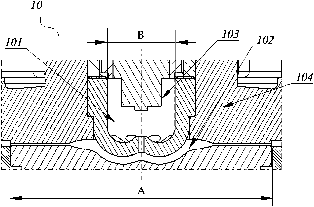
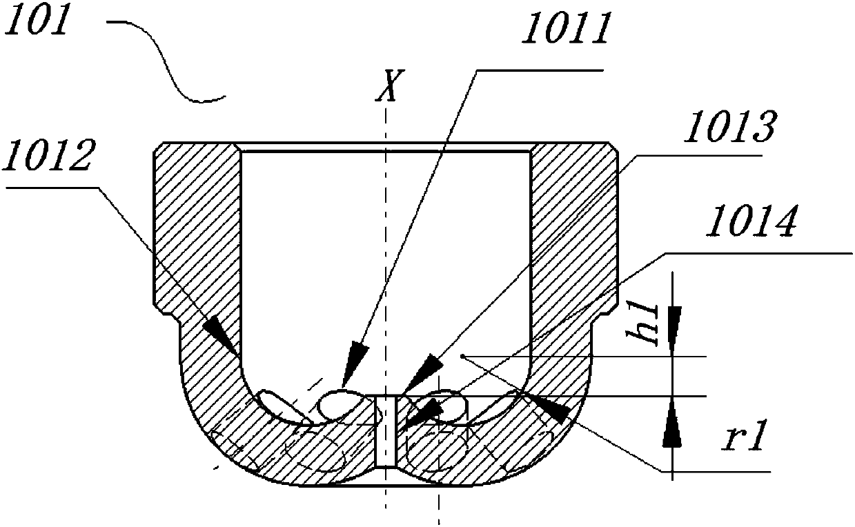
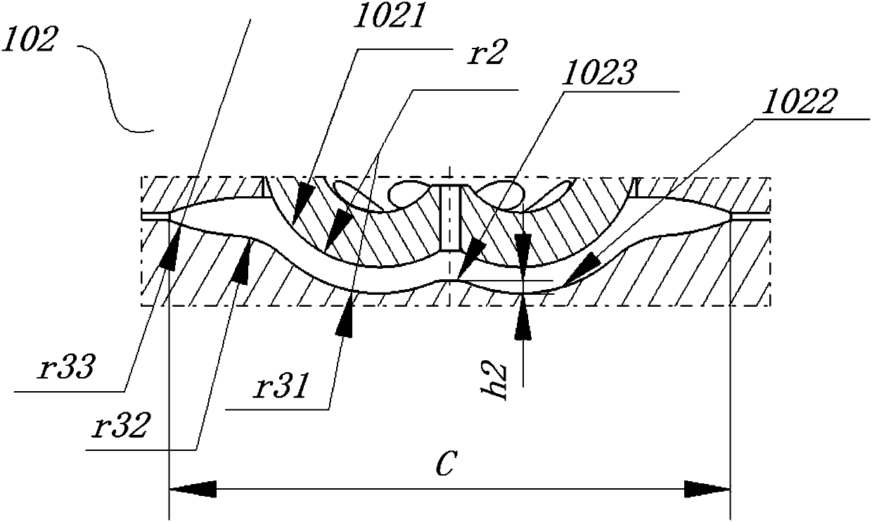
[0027] figure 1 It is a longitudinal sectional view of a combined combustion chamber for a piston engine according to an embodiment of the present application, wherein the combined combustion chamber includes a strong swirl secondary combustion chamber 101 and a swirl main combustion chamber 102 . figure 2 is a longitudinal sectional view of the auxiliary combustion chamber. image 3 is a longitudinal sectional view of the main combustion chamber. It should be understood that the "vortex" in this article is one of the motion forms of the "swirl".

[0028] Such as figure 1 As shown, the strong swirl secondary combustion chamber 101 is formed ...


PUM


Abstract

The invention discloses a combined combustion chamber used for a piston engine. The combined combustion chamber comprises an air cylinder head, an auxiliary combustion chamber formed in the air cylinder head, and a main combustion chamber formed among the air cylinder head, the auxiliary combustion chamber and a piston. The auxiliary combustion chamber communicates with the main combustion chamberthrough multiple first channels arranged at the bottom of the auxiliary combustion chamber, and the center lines of the first channels are arranged in a bias manner in the radial direction relative to the center line of the auxiliary combustion chamber. High-strength vortexes are forcefully formed and maintained in the auxiliary combustion chamber so that the combustion speed of the engine can beobviously increased, the highest explosion pressure is controlled, the fuel economy is improved, and the requirement for high safety of the aircraft engine is met.

Description

technical field [0001] The present application relates to the field of piston engine combustion chambers, specifically but not exclusively, to a multi-channel combined combustion chamber for two-stroke aviation heavy oil piston engines. Background technique [0002] In recent years, two-stroke aviation heavy oil piston engines have played an increasingly important role in small aircraft and unmanned aerial vehicles. Among them, the reasonable organization and good combustion of the airflow in the combustion chamber of the heavy fuel oil piston engine will directly affect the performance and working efficiency of the heavy fuel oil engine. Therefore, the optimization of the shape of the combustion chamber will greatly promote the development of the heavy fuel oil engine. . [0003] The heavy oil engine combustion chambers involved in the prior art can be divided into open type, semi-open type, vortex type and pre-combustion type combustion chambers according to the different...

Claims


Application Information

Patent Timeline
Patent Type & Authority Applications(China)
IPC IPC(8): F02B23/00F02B19/08F02B19/10F02B19/18F02F1/24
CPCY02T10/12
Inventor 韩树军杜发荣徐征周煜张向波
Owner 北京领动国创科技有限公司
Why Eureka
Try Eureka