High-precision circular marking point center positioning method in large-distortion lens and device thereof

A center positioning and marking point technology, applied in the field of optical measurement, can solve the problems of high cost, inaccurate center positioning of circular marking points, and increased system cost, and achieve the effect of solving inaccurate positioning.

Active Publication Date: 2018-01-26
SHENZHEN UNIV
View PDF9 Cites 11 Cited by
  • Summary
  • Abstract
  • Description
  • Claims
  • Application Information

AI Technical Summary

Problems solved by technology

However, this method of improving the hardware will increase the system cost sharply, and this hardware improvement cannot reduce the perspective projection error of the center positioning of the circular marker point, because this error is due to the fact that the camera imaging plane is not parallel to the marker point The hardware improvement brought by the plane can only reduce a small part of the center positioning error, and the cost is very high
[0004] Both the lens distortion and the perspective projection of the center of the circular marker point will cause the positioning error of the center of the circular marker point, resulting in inaccurate positioning of the center of the circular marker point

Method used


Image

  • High-precision circular marking point center positioning method in large-distortion lens and device thereof
  • High-precision circular marking point center positioning method in large-distortion lens and device thereof
  • High-precision circular marking point center positioning method in large-distortion lens and device thereof

Examples


Embodiment Construction

[0040] In order to make the object, technical solution and advantages of the present invention clearer, the present invention will be further described in detail below in conjunction with the accompanying drawings and embodiments. It should be understood that the specific embodiments described here are only used to explain the present invention, not to limit the present invention.

[0041] In the prior art, both lens distortion and perspective projection of the center of the circular marker point will lead to a positioning error of the center of the circular marker point, thus resulting in a technical problem of inaccurate positioning of the center of the circular marker point.

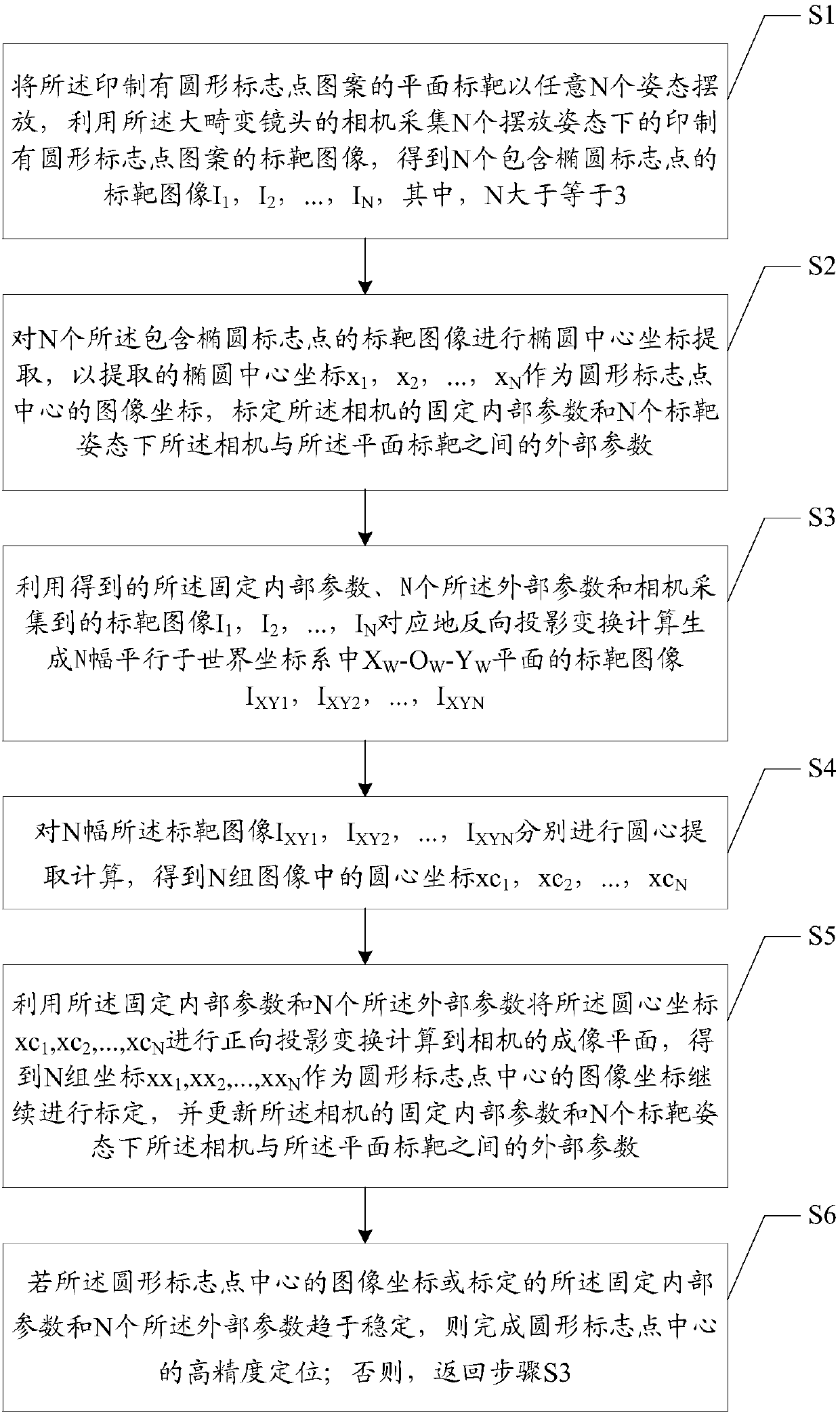
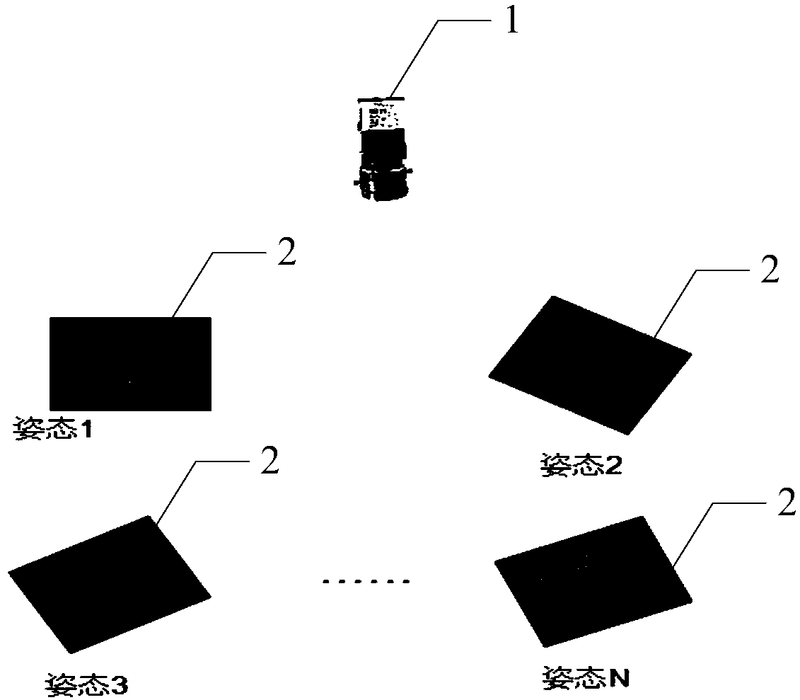
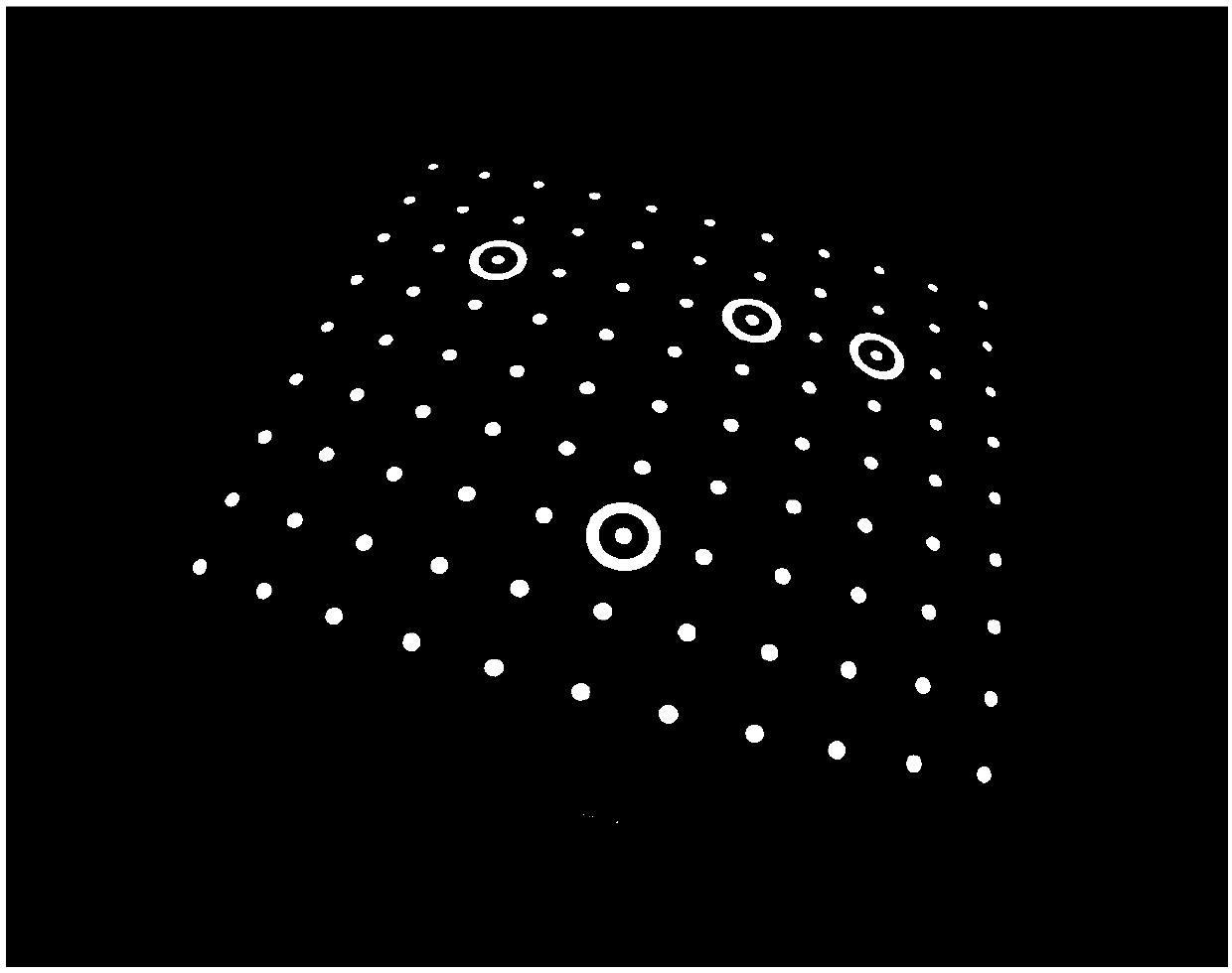
[0042] In order to solve the above technical problems, the present invention proposes a high-precision circular marker point center positioning method and device under a large distortion lens, using a flexible and simple software algorithm to reduce the circular markers caused by lens distortion and pe...


PUM


Abstract

The invention is suitable for the field of optical measurement technology, and provides a high-precision circular marking point center positioning method in a large-distortion lens and a device thereof. The method comprises the steps of firstly, acquiring N target images with printed circular marking point patterns in a placement attitude by means of a camera of the large-distortion lens, and obtaining N target images; then, performing elliptical central coordinate extraction on the target image, and calibrating a fixed inner parameter of the camera and N external parameters; then, performingreversed projection conversion calculation for generating N target images which are parallel with an XW-OW-YW plane in a world coordinate system; performing circle center extraction calculation on theN target images, and performing forward projection conversion for calculating an imaging plane to the camera; obtaining N sets of coordinates as the image coordinate of the circular marking point center and continuously performing calibration, and updating the fixed inner parameter and the N external parameters; and if the image coordinate of the circular marking point center is stable, finishingpositioning. The method according to the invention realizes high-precision circular marking point center positioning.

Description

technical field [0001] The invention belongs to the technical field of optical measurement, in particular to a method and device for positioning the center of a high-precision circular marker point under a large distortion lens. Background technique [0002] The use of circular markers has been used for decades, and the research on the high-precision positioning algorithm of the center of circular markers is an enduring subject. As a kind of artificial landmarks, circular landmarks are widely used in key links in the field of optical three-dimensional measurement such as the calibration of imaging systems and depth image matching. In the calibration system, good calibration results can provide very critical data for the optical three-dimensional measurement system. High-precision calibration results have always been the unremitting pursuit in the field of optical three-dimensional measurement, and the center coordinates of the circular marker point are the most important inp...

Claims


Application Information

Patent Timeline
Patent Type & Authority Applications(China)
IPC IPC(8): G06T7/70G06T7/80
Inventor 彭翔张雅琴刘晓利蔡泽伟
Owner SHENZHEN UNIV
Why Eureka
Try Eureka