Method and device for producing a fiber composite material

A technology of fiber composite materials and composite materials, which is applied in the field of composite material production and can solve problems such as unstable methods

Active Publication Date: 2018-01-26
EVONIK OPERATIONS GMBH
View PDF6 Cites 3 Cited by
  • Summary
  • Abstract
  • Description
  • Claims
  • Application Information

AI Technical Summary

Problems solved by technology

There is also a risk of uncontrolled fiber breakage which destabilizes the entire process

Method used


Image

  • Method and device for producing a fiber composite material
  • Method and device for producing a fiber composite material

Examples


Embodiment Construction

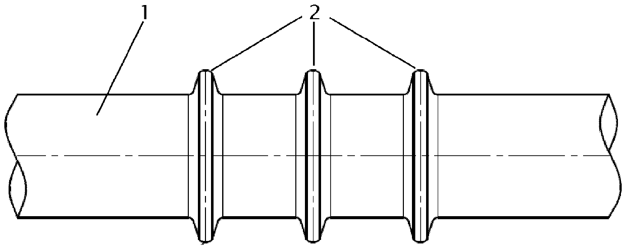
[0034] figure 1 The deflection rod 1 depicted in has three radially surrounding projections 2 which, in this case, are arranged in the region of the deflection rod above which the fiber bundle is guided.

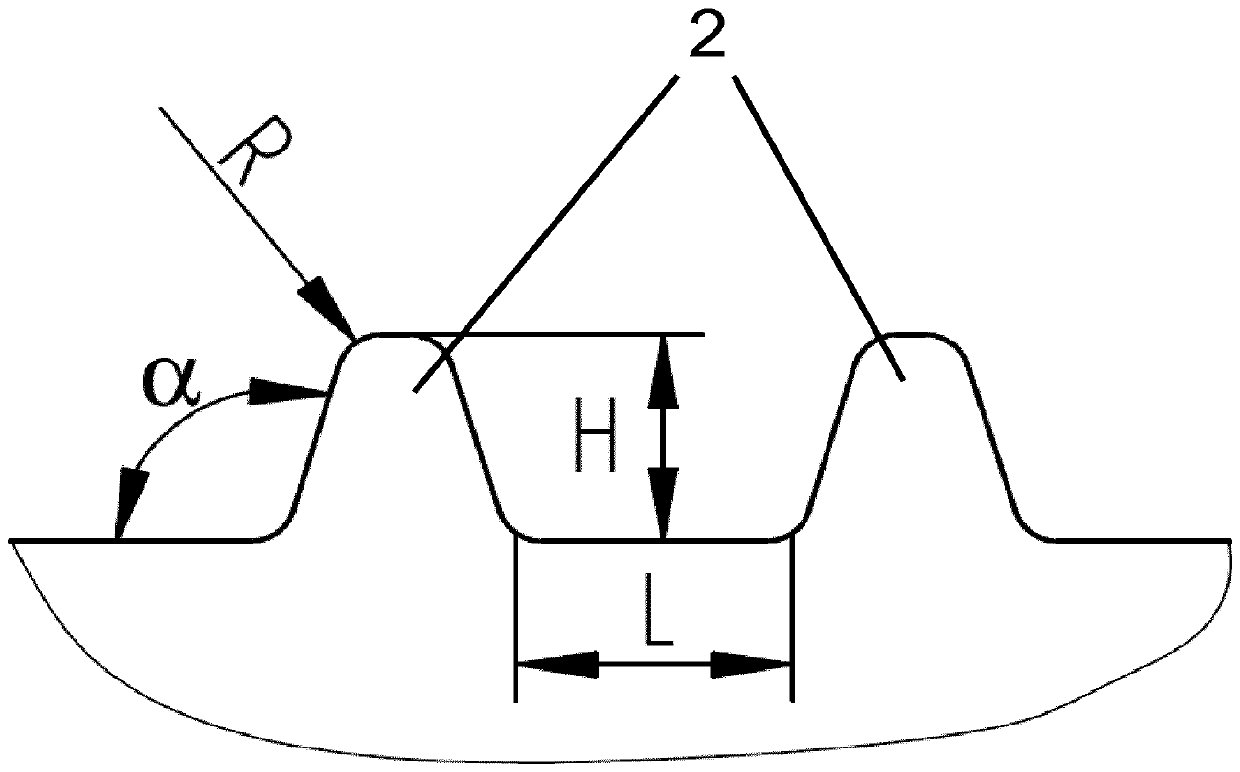
[0035] figure 2 More specifically two protrusions 2 are illustrated. The protrusion has a side angle α, a height H, and a radius R with a rounded tip. Located between the protrusions are straight sections of length L, which may be, for example, 0.5 to 6 times the width of the original roving. The side angle α is preferably 90.1° to 100°, especially preferably 90.3° to 95°, and particularly preferably 90.5° to 92°, while the height H is preferably 0.2 mm to 20 mm, especially preferably 0.5 mm to 10 mm, particularly preferably 1 mm to 6 mm, and very particularly preferably 2 mm to 4 mm. The radius R is preferably 0.1 mm to 10 mm, particularly preferably 0.1 mm to 5 mm, and particularly preferably 0.2 to 2 mm. The radius is based on rounding the tip.

[0036] A particula...


PUM

PropertyMeasurementUnit
Lengthaaaaaaaaaa
Heightaaaaaaaaaa

Abstract

The invention relates to a method for producing a fiber composite material, comprising the following steps: a) a fiber bundle is guided over at least one deflection rod (1), which has radially peripheral rounded elevations (2), and said fiber bundle is thereby expanded; b) the expanded fiber bundle is subsequently drawn into an impregnation chamber; c) a melt is applied onto the expanded fiber bundle; d) the fiber bundle impregnated with melt is pulled through a draw-off nozzle at the tool end. The invention is characterized that a very good impregnation quality is achieved by said method anda corresponding device.

Description

technical field [0001] The invention relates to a method and a device for producing composite materials, in which one or more fiber bundles can be gently expanded and subsequently impregnated with a melt. The method / apparatus also allows for optimal expansion of more cost-effective fiber types (eg, fibers composed of E-glass) with minimal fiber breakage. Background technique [0002] The unraveling of fiber bundles during impregnation is known. A common way of fiber expansion is to spread out the fiber bundle by adding deflection via various deflection rods. Depending on the number of rods, good deflection angles and surface quality can be achieved this way. In principle, high levels of fiber expansion are achieved by increasing deflection. However, this process leads to breakage of individual filaments in the fiber bundle, which hinders further processing and destabilizes the handling operation. Conversely, complete fiber spreading cannot be achieved with smaller deflec...

Claims


Application Information

Patent Timeline
IPC IPC(8): B29B15/12
CPCB29B15/122B29B9/06B29B9/10B29B9/14B29C43/24
Inventor M.R.贝尔林U.宋德曼
Owner EVONIK OPERATIONS GMBH
Why Eureka
Try Eureka