
Multiple beam additive manufacturing

An additive manufacturing, multi-beam technology used in the field of additive manufacturing

Inactive Publication Date: 2018-01-26
IPG PHOTONICS CORP
View PDF1 Cites 23 Cited by
  • Summary
  • Abstract
  • Description
  • Claims
  • Application Information

AI Technical Summary

Problems solved by technology

Attempts to use multiple beams in SLM systems have failed because of the challenges involved in scanning the same area with multiple beams

Method used


Image

  • Multiple beam additive manufacturing
  • Multiple beam additive manufacturing
  • Multiple beam additive manufacturing

Examples


Embodiment Construction

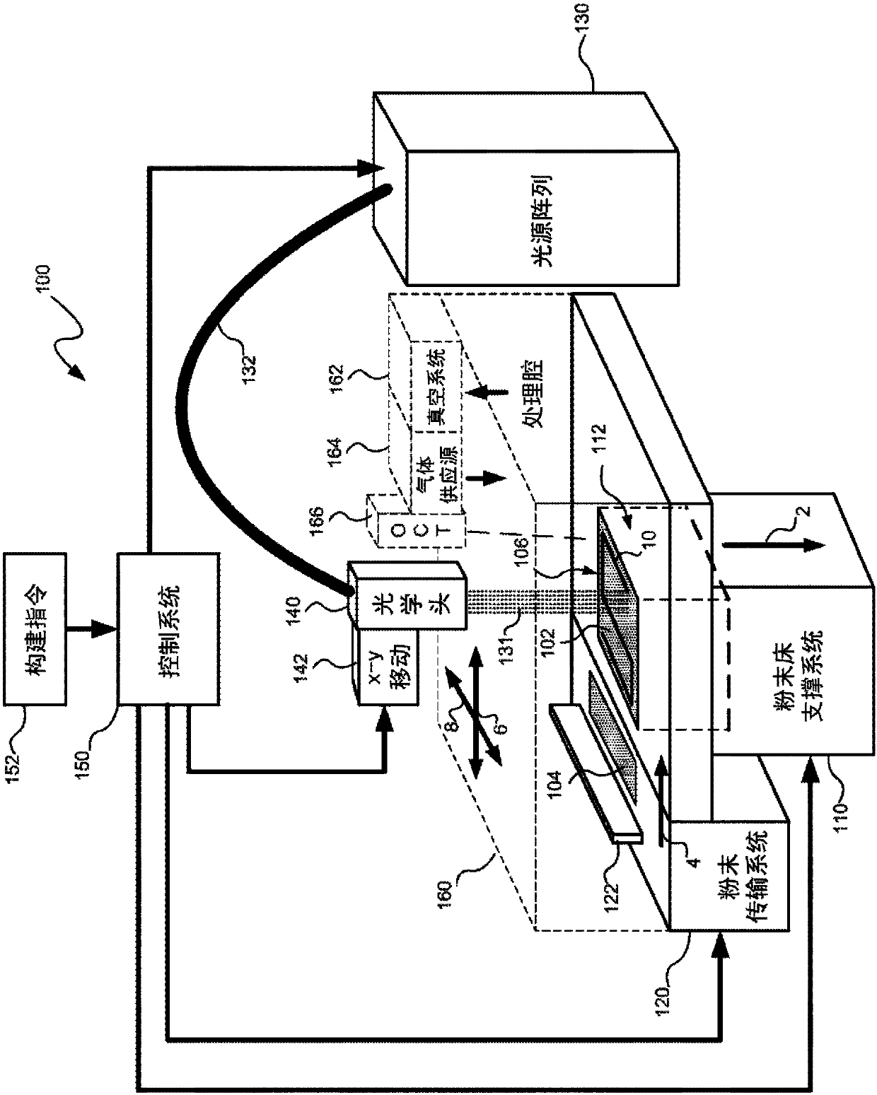
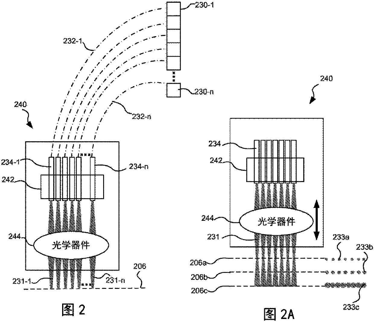
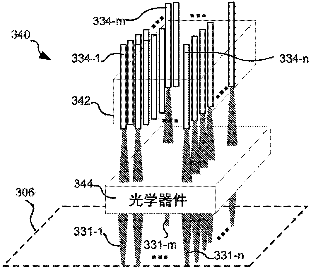
[0039] Systems and methods for multi-beam additive manufacturing consistent with the present disclosure use multiple beams of light (e.g., lasers) to expose a layer of powder material in selected areas until the powder material melts to form voxels, which form three-dimensional structured build layers. Light can be generated from a selected light source and coupled into an array of optical fibers having outputs arranged in at least one row in the optical head so that multiple beams are sequentially directed by the optical head to the same powder area, thereby providing a multi-beam Sequential exposures (eg, preheating, melting, and controlled cooling) fuse the powder regions. Multiple sequential beams can be moved using various techniques (eg, by moving an optical head) and according to various scanning patterns, such that multiple fused regions form each buildup layer.

[0040] By providing a multi-beam sequential exposure with varying intensities over the area of ​​the powd...


PUM

PropertyMeasurementUnit
power outputaaaaaaaaaa
diameteraaaaaaaaaa
wavelengthaaaaaaaaaa

Abstract

Systems and methods for multiple beam additive manufacturing use multiple beams of light (e.g., laser light) to expose layers of powder material in selected regions until the powder material fuses toform voxels, which form build layers of a three-dimensional structure. The light may be generated from selected light sources and coupled into an array of optical fibers having output ends arranged inan optical head in at least one line such that multiple beams are sequentially directed by the optical head to the same powder region providing multiple beam sequential exposures (e.g., with pre-heating, melting and controlled cool down) to fuse the powder region. The multiple sequential beams may be moved using various techniques (e.g., by moving the optical head) and according to various scan patterns such that a plurality of fused regions form each build layer.

Description

[0001] Related Application Cross Reference [0002] This application claims the benefit of US Patent Application Serial No. 62 / 173,541 filed June 10, 2015, which is hereby incorporated by reference in its entirety. technical field [0003] The present disclosure relates to additive manufacturing, and more particularly to multi-beam additive manufacturing. Background technique [0004] Additive manufacturing (also known as 3D printing) technology has been used to create three-dimensional structures of almost any shape. Using an additive process, successive layers of material are deposited to form a structure based on data defining a 3D model of the structure. In some methods known as powder bed fusion (PBF), structures are produced by depositing successive layers of powder material and using a beam of light (such as a laser) to combine or fuse the powder material in selected regions of each layer. successive layers. Examples of these methods include selective laser sinteri...

Claims


Application Information

Patent Timeline
Patent Type & Authority Applications(China)
IPC IPC(8): B29C64/153B29C64/30B29C64/321B33Y30/00B33Y40/00
CPCB33Y10/00B29C64/153B23K2103/08B33Y30/00B33Y50/02B29C64/277B29C64/268Y02P10/25B22F10/28B22F10/366B22F12/45B22F12/47B22F2999/00B22F12/41B22F10/36B22F12/49B22F12/52B23K26/082B23K26/342B23K26/0604B23K26/0626B23K26/073B23K26/0869B33Y70/10
Inventor 约瑟夫·达拉罗萨威廉·欧内尔马丁·斯帕克斯安德鲁·佩恩
Owner IPG PHOTONICS CORP
Learn More