Building block lap joint structure

A technology of connecting structures and building blocks, which is applied in the field of toys, can solve problems such as insufficient connection, poor playability, and easy collapse of building blocks, and achieve the effect of simple structure, strong connection firmness, and high playability

Inactive Publication Date: 2018-01-30
黄芳
View PDF1 Cites 0 Cited by
  • Summary
  • Abstract
  • Description
  • Claims
  • Application Information

AI Technical Summary

Problems solved by technology

[0004] The above solution solves the problem that the existing building blocks are easy to collapse to a certain extent, and improves the stability of the building bloc

Method used


Image

  • Building block lap joint structure
  • Building block lap joint structure

Examples


Example Embodiment

[0021] Example one

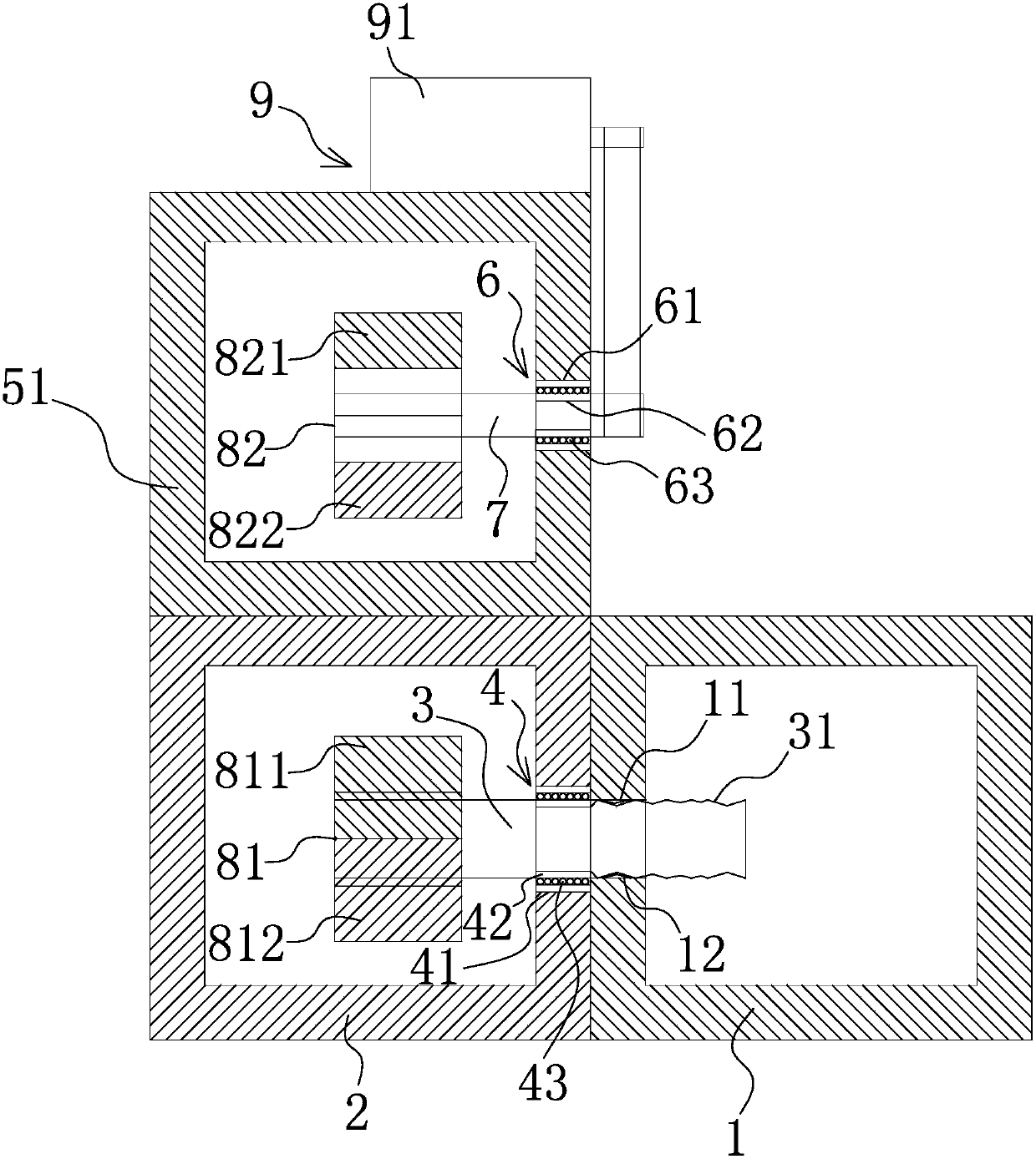
[0022] Such as figure 1 As shown, the building block lap structure includes a connecting post 3 arranged on a polyhedral adapter block 2 with an inner cavity through a first rotating mounting structure 4, the connecting post 3 penetrates the inner cavity and the At least one end of the connecting column 3 extends to the outside of the adapter block 2. At least one side of the adapter block 2 is provided with a polyhedral building block 1, and the building block 1 has an end portion for the connecting column 3 to be inserted The connecting hole 11 has an internal thread 12 in the connecting hole 11, and the end of the connecting column 3 extending to the outside of the adapter block 2 has an external thread 31 engaged with the internal thread 12, the connecting column 3 One end in the inner cavity is provided with a first magnetic body 81 having a first S pole 811 and a first N pole 812, and the upper or lower end of the adapter block 2 is provided with a poly...

Example Embodiment

[0028] Example two

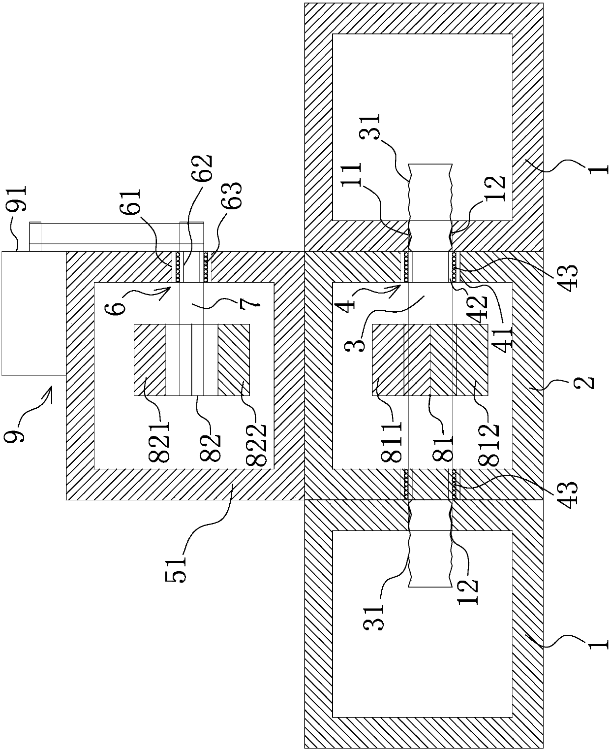
[0029] Such as figure 2 As shown, the structure, principle, and implementation steps of this embodiment are similar to those of Embodiment 1. The difference is that the two ends of the connecting column 3 in this embodiment extend to the outside of the adapter block 2 respectively, and the first magnetic body 81 is annular, the first magnetic body 81 is sleeved in the middle of the connecting column 3 and the first magnetic body 81 and the connecting column 3 are coaxially arranged, and the first S pole 811 and the first N pole 812 are both The arc block shape and the two radially spliced ​​together form the first magnetic body 81 mentioned above,

[0030] In other words, both ends of the connecting column 3 extending to the outside of the adapter block 2 have external threads 31, and the thread directions of the two sections of external threads 31 are opposite. Here, the connecting post 3 in the adapter block 2 is used to overlap the two building block bloc...


PUM


Abstract

The invention relates to a building block lap joint structure. The problem is solved that the design in the prior art is not reasonable. The building block lap joint structure comprises a connecting column arranged on an adapting connection block, wherein the connecting column penetrates into an inner cavity, at least one end of the connecting column extends to the outer side of the adapting connection block, a building block is arranged on at least one side of the adapting connection block and is provided with a connecting hole, an inner thread is arranged in the connecting hole, an outer thread meshed with the inner thread is arranged at the end, extending to the outer side of the adapting connection block, of the connecting column, a first magnetic body is arranged at one end of the connecting column, a control seat is arranged at the upper end or the lower end of the adapting connection block, a rotary rod is arranged on the control seat, one end of the rotary rod is located in thecavity, a second magnetic body is arranged at the end of the rotary rod, the other end of the rotary rod extends to the outer side of the control seat and is connected with a rotary driving mechanism. The building block lap joint structure has the advantages that bolt rotation is controlled by utilizing the principle that same charges of the magnetic bodies repulse each other and opposite chargesof the magnetic bodies attract each other, two or three building blocks are connected in a threaded mode through magnetic control, the connecting firmness is strong, and the playability is high.

Description

technical field [0001] The invention belongs to the technical field of toys, and in particular relates to a building block overlapping structure. Background technique [0002] Building blocks are usually cubic wooden or plastic solid toys, usually decorated with letters or pictures on each surface, allowing different arrangements or construction activities. Building blocks have various styles, which can develop children's intelligence and can be assembled into houses and various animals. Wait. There are two main types of traditional building block toys, the first is wooden building blocks, the building blocks can be placed in different shapes, and there are no connecting parts between the building blocks; the second is plug-in building blocks; these two kinds of building blocks exist The big problem is that the first type of building blocks tends to collapse during placement; the second type of building blocks is prone to difficulty in plugging in and out or jamming. This ...

Claims


Application Information

Patent Timeline
IPC IPC(8): A63H33/04A63H33/12
Inventor 黄芳
Owner 黄芳
Why Eureka
Try Eureka