Cohesive soil cleaning device for cutter

A cleaning device and cohesive soil technology, which is applied in the direction of mechanically driven excavators/dredgers, etc., can solve the problem of cohesive soil clogging the reamer, avoid the clogging of the reamer head, avoid cohesive soil unity, and ensure construction efficiency effect

Inactive Publication Date: 2018-01-30
CCCC SHANGHAI DREDGING
View PDF6 Cites 0 Cited by
  • Summary
  • Abstract
  • Description
  • Claims
  • Application Information

AI Technical Summary

Problems solved by technology

This utility model can only prevent large-grained stones from entering the suction port, but cannot solve the problem of cohesive soil blocking the reamer

Method used


Image

  • Cohesive soil cleaning device for cutter
  • Cohesive soil cleaning device for cutter
  • Cohesive soil cleaning device for cutter

Examples


Embodiment Construction

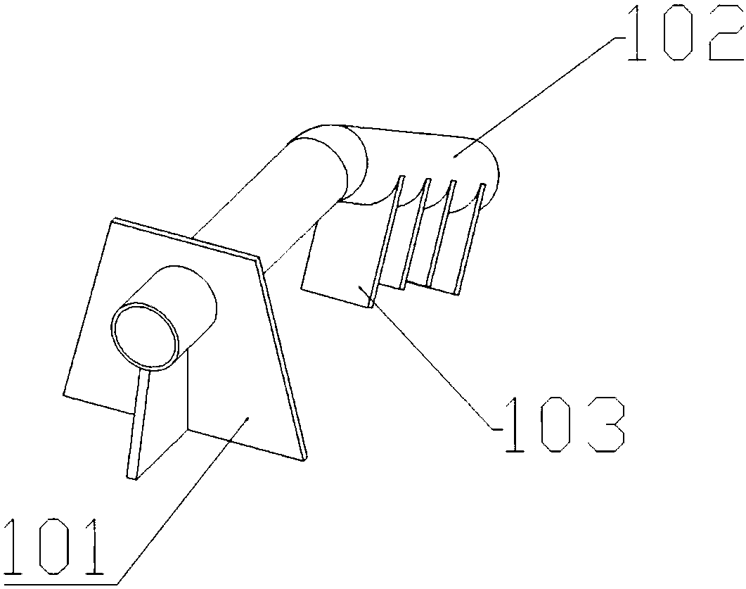
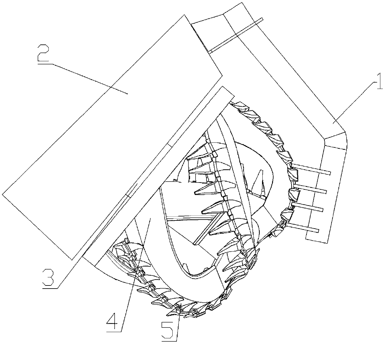
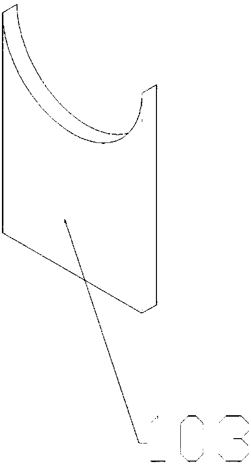
[0022] Such as figure 1 with figure 2 As shown, the sticky soil cleaning device 1 of the present invention comprises a base 101, a blade holder 102 welded on the base 101, at least one soil scraping blade 103 welded on the blade holder 102, and the soil scraping blade 103 It is arranged between two reamer teeth 5 on the reamer head 4 , the thickness and length of the soil scraping blade 103 are matched with the reamer teeth 5 , and the base 101 is welded on the bridge frame 2 . The reamer head 4 is installed on the bridge frame 2 through the reamer shaft 3 .

[0023] The working principle of the present invention is as follows: the reamer head 4 is installed on the bridge frame 2 by the reamer shaft 3 and rotates to break the soil. The cohesive soil between the reamer teeth 5 is scraped off, thereby avoiding the cohesion of the cohesive soil between the reamer teeth 5 .

[0024] As a preferred embodiment, the base 101 is composed of a bottom plate and reinforcing ribs, and...


PUM


Abstract

The invention relates to a cohesive soil cleaning device for a cutter. The cohesive soil cleaning device comprises a base, a knife holder welded to the base, and at least one soil scraping blade welded to the knife holder, wherein the soil scraping blade is arranged between the two cutter teeth on the cutter head, the thickness and the length of the soil scraping blade are matched with the cutterteeth. The cohesive soil cleaning device for the cutter can automatically remove the cohesive soil adhered between the cutter teeth in time to prevent the cohesive soil from solidification between thecutter teeth, thereby avoiding the occurrence of blocking of the cutter head and ensuring the construction efficiency of the cutter suction dredger.

Description

technical field [0001] The invention relates to the technical field of dredging engineering, in particular to a cohesive soil cleaning device for a reamer. Background technique [0002] Due to the strong adhesion of cohesive soil, in the process of dredging cohesive soil, it is often encountered that the reamer head is covered by cohesive soil, thereby blocking the gap between the reamers and finally blocking the knife. After the knife is blocked, the construction can only be suspended, and the construction can only be continued after the cohesive soil attached to the reamer is removed manually with an engineer shovel, which seriously affects the construction efficiency. [0003] Due to the unfavorable conditions such as low flow velocity and low suction vacuum between the cutter arms at the hub end of the reamer head compared to the cutter arms at the large circle end, the cohesive soil tends to gather at the hub section, unite together and gradually spread to the large cir...

Claims


Application Information

Patent Timeline
Patent Type & Authority Applications(China)
IPC IPC(8): E02F3/92
Inventor 陶冲林陈旭李晟嵇文远杨增海
Owner CCCC SHANGHAI DREDGING
Why Eureka
Try Eureka