Clutch separation system and clutch driven cylinder

A technology of clutches and cylinders, applied in the field of clutches, can solve the problems of high manufacturing cost and difficult demoulding, and achieve the effects of reducing installation costs, improving assembly convenience, and being easy to implement

Inactive Publication Date: 2018-01-30
SCHAEFFLER TECH AG & CO KG
View PDF10 Cites 1 Cited by
  • Summary
  • Abstract
  • Description
  • Claims
  • Application Information

AI Technical Summary

Problems solved by technology

When using the mold forming process to manufacture the cylinder block of the clutch slave cylinder, since it is necessary to form a press-fit groove on the inner peripheral surface of the cylinder body, it is difficult to achieve demoulding after mold forming
In order to realize the demoulding of the inner peripheral surface with the press-fitting groove, it is necessary to carry out complex design of the mold used to manufacture the cylinder body of the clutch slave cylinder, resulting in high manufacturing cost

Method used


Image

  • Clutch separation system and clutch driven cylinder
  • Clutch separation system and clutch driven cylinder

Examples


Embodiment Construction

[0021] In order to make the above objects, features and advantages of the present invention more comprehensible, specific embodiments of the present invention will be described in detail below in conjunction with the accompanying drawings.

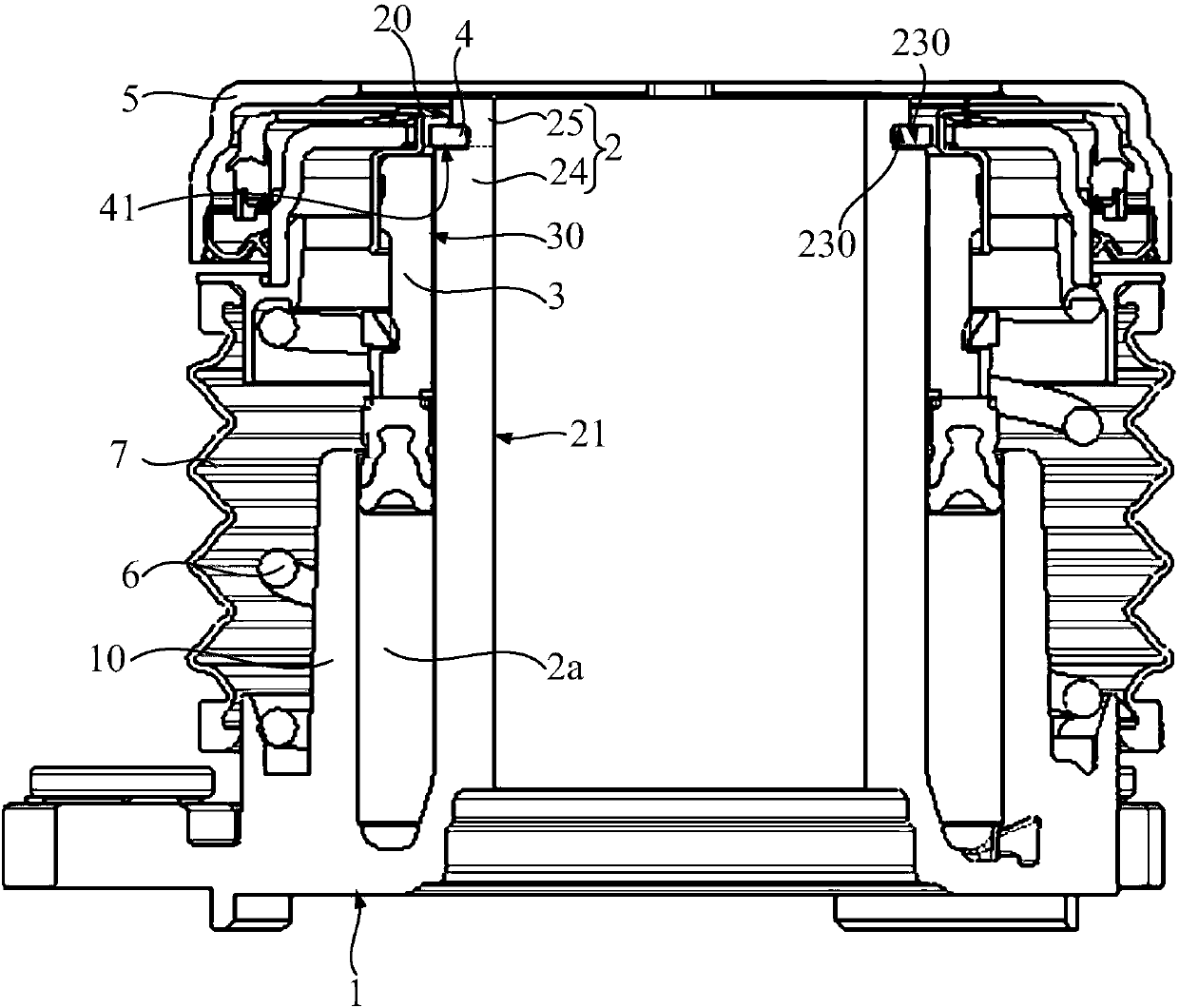
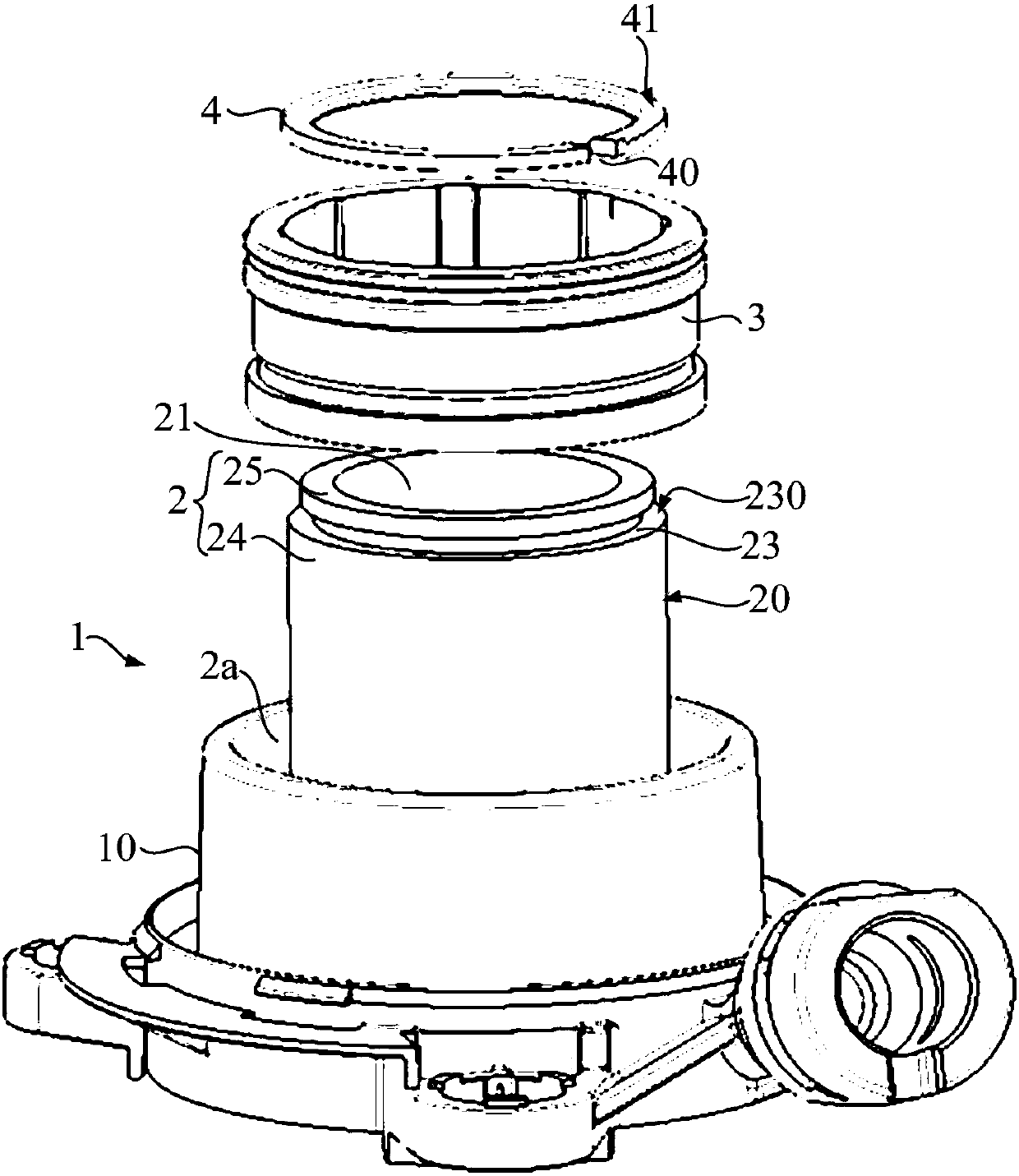
[0022] The clutch release system includes the clutch slave cylinder. refer to figure 1 and figure 2 , The clutch slave cylinder 1 includes: a cylinder body 2, a piston 3 and a stopper 4 arranged on the cylinder body 2. The cylinder body 2 is provided with an annular pressure chamber 2a, the pressure chamber 2a surrounds the central axis of the cylinder body 2, and the piston 3 is used to reciprocate in the pressure chamber 2a along the axial direction of the cylinder body 2; the stopper 4 is located on the piston 3 along the axis The side away from the pressure chamber 2 a is used to prevent the piston 3 from falling off the cylinder body 2 . When the pressure chamber 2a is filled with oil, the piston 3 moves toward the stopper 4, and ...


PUM


Abstract

Provided are a clutch separation system and a clutch driven cylinder. The clutch driven cylinder includes a cylinder body, a piston and a blocking part arranged on the cylinder body; the cylinder bodyis provided with an annular pressure cavity which arranged around a middle axis of the cylinder body, and the piston is used for moving back and forth in the axial direction of the cylinder body in the pressure cavity; the blocking part is located at one side, away from the interior of the pressure cavity, of the piston in the axial direction, used for preventing the piston from detaching from the cylinder body and installed on the outer circumferential surface of the cylinder body. By utilizing the technical scheme, the blocking part is installed on the outer circumferential surface of the cylinder body and has no intersection with the inner circumferential surface of the cylinder body, the inner circumferential surface does not need to be improved, and after a die is shaped, the demoulding process of the cylinder body from the inner circumferential surface is easy to complete; the die used for manufacturing the cylinder body of the clutch driven cylinder is simple in design, easy toachieve and low in manufacturing cost. Moreover, since the outside space of the cylinder body is large, a large operation space can be provided for assembly processes of the blocking part and the outer circumferential surface of the cylinder body, the assembly convenience is improved, and the installation cost is reduced.

Description

technical field [0001] The invention relates to the technical field of clutches, in particular to a clutch separation system and a clutch slave cylinder. Background technique [0002] The existing clutch disengagement system includes: a clutch slave cylinder for controlling the disengagement and engagement of the clutch. The clutch slave cylinder includes: a cylinder body, a piston sleeved outside the cylinder body and a stop ring arranged on the cylinder body. The cylinder body is provided with an annular pressure chamber, the pressure chamber surrounds the central axis of the cylinder body, and the piston is used for reciprocating movement along the axial direction of the cylinder body in the pressure chamber. The stop ring is located on the side of the piston away from the pressure chamber in the axial direction, and at least partly overlaps the piston in the radial direction, and is used to prevent the piston from falling off from the cylinder body. [0003] Wherein, t...

Claims


Application Information

Patent Timeline
Patent Type & Authority Applications(China)
IPC IPC(8): F16D25/12F15B15/24F16J10/02
CPCF15B15/24F16D2300/12F16D25/083
Inventor 张斌奥尔多·亨利克·基洛托·马法拉奇法比奥·路易斯·维埃拉
Owner SCHAEFFLER TECH AG & CO KG
Why Eureka
Try Eureka