Smelting dross filter tank with fan blades

A fan blade and slag filter technology, applied in the field of smelting, can solve the problems of indeterminate flow, waste, low slag removal efficiency, etc., and achieve the effect of improving production efficiency and improving safety

Inactive Publication Date: 2018-02-02
路望培
View PDF1 Cites 1 Cited by
  • Summary
  • Abstract
  • Description
  • Claims
  • Application Information

AI Technical Summary

Problems solved by technology

[0002] Most of the technologies use skimmers to remove the scum on the molten water. The skimmers have the disadvantages of troublesome operation, and often bring good water out, resulting in waste. Another is to install it on the molten water transfer device. Filter plate, it has the shortcoming that it is difficult to control the scum, and the scum is easy to mix. In the existing technology, the application number is 201320260704.3 "a kind of smelting filter slag tank with fan blades", and there are also the following disadvantages: 1. The floating speed of scum Slow, resulting in scum mixed in the drainage outlet; 2. The efficiency of slag removal is low, which cannot meet the continuous water injection and the operation of variable flow; 3. When molten water is introduced into the filter slag tank, it is easy to gushes out

Method used


Image

  • Smelting dross filter tank with fan blades
  • Smelting dross filter tank with fan blades

Examples


Embodiment Construction

[0018] The principles and features of the present invention are described below in conjunction with the accompanying drawings, and the examples given are only used to explain the present invention, and are not intended to limit the scope of the present invention.

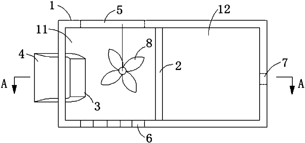
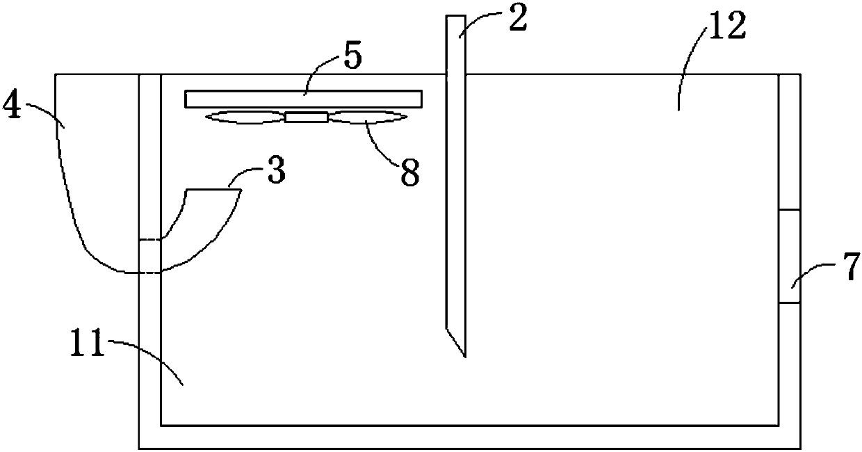
[0019] Such as figure 1 with figure 2 As shown, a smelting filter slag tank with fan blades includes a tank body 1, the tank body 1 is made of refractory material, the tank body 1 includes a first sub-channel 11 and a second sub-channel 12, the Between the first sub-groove 11 and the second sub-groove 12, a partition plate 2 movable in the vertical direction is arranged, and a water inlet 3 is arranged on the inner side of the side of the first sub-groove 11, and the water inlet 3. The opening faces upward, and a water receiving port 4 is provided on the outer surface of the corresponding side of the water inlet 3. The water receiving port 4 communicates with the water inlet 3. The adjacent side of the side where ...


PUM


Abstract

The invention relates to a smelting filter slag tank with fan blades, which includes a tank body made of refractory materials, the tank body includes a first sub-channel and a second sub-channel, and the gap between the first sub-channel and the second sub-channel is A partition plate movable in the vertical direction is provided, a water inlet is arranged on the inner surface of the side of the first sub-groove, and the opening of the water inlet faces upward, and a water inlet is arranged on the outer surface of the corresponding side of the water inlet, and the water inlet It communicates with the water inlet, a slag outlet is provided on the side adjacent to the side where the water inlet is located, and at least one fan is provided on the upper end of the other adjacent side of the side where the water inlet is located, and the second sub-groove The side part is provided with a drain port; the inner side of the first sub-trough is provided with fan blades, and the fan blades are corresponding to the liquid level in the first sub-trough; the fan blades are connected to the tank body through a connecting rod The side wall is connected, and the fan blade is rotatably connected with the connecting rod. Compared with the prior art, the invention has fast scum floating up, high slag removal efficiency, and can realize continuous operation.

Description

technical field [0001] The invention relates to the technical field of smelting, in particular to a smelting residue tank with fan blades. Background technique [0002] Most of the technologies use skimmers to remove the scum on the molten water. The skimmers have the disadvantages of troublesome operation, and often bring good water out, resulting in waste. Another is to install it on the molten water transfer device. Filter plate, it has the shortcoming that it is difficult to control the scum, and the scum is easy to mix. In the existing technology, the application number is 201320260704.3 "a kind of smelting filter slag tank with fan blades", and there are also the following disadvantages: 1. The floating speed of scum 2. The efficiency of slag removal is low, which cannot meet the operation of continuous water injection and flow rate; 3. When molten water is introduced into the filter slag tank, it is easy to gush out. Contents of the invention [0003] The technical...

Claims


Application Information

Patent Timeline
Patent Type & Authority Applications(China)
IPC IPC(8): B22D43/00
CPCB22D43/001
Inventor 路望培
Owner 路望培
Why Eureka
Try Eureka