
Novel unmanned aerial vehicle for pesticide spraying

A technology of pesticide spraying and unmanned aerial vehicles, which is applied in the field of agricultural machinery, can solve the problems of slow development of agricultural unmanned aerial vehicles, narrow scope of use, short battery life, etc., and achieve energy-saving and high-efficiency applicable scope, convenient operation and use, and increased applicability Effect

Inactive Publication Date: 2018-02-02
刘晓东
View PDF0 Cites 3 Cited by
  • Summary
  • Abstract
  • Description
  • Claims
  • Application Information

AI Technical Summary

Problems solved by technology

[0002] At present, the unmanned aircraft is referred to as "UAV" for short, and the English abbreviation is "UAV". It is an unmanned aircraft controlled by radio remote control equipment and its own program control device. Many drone companies have been established, but the development of agricultural drones is slow. The existing agricultural drones have a narrow range of applications, small loads, short battery life, and difficult operation; therefore, in order to solve the above problems, it is necessary to develop an easy-to-use A new type of pesticide spraying drone that is energy-saving, efficient and widely applicable is necessary

Method used


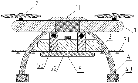
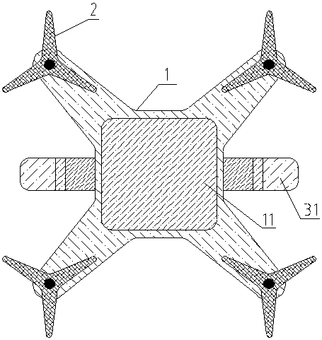
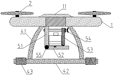
Image

  • Novel unmanned aerial vehicle for pesticide spraying
  • Novel unmanned aerial vehicle for pesticide spraying
  • Novel unmanned aerial vehicle for pesticide spraying

Examples


Embodiment Construction

[0016] The present invention will be further described below in conjunction with the accompanying drawings.

[0017] Such as figure 1 , figure 2 , image 3 , Figure 4 Shown: a new type of pesticide spraying drone, including a body 1, a rotor 2, a pesticide box 3 and a landing bracket 4, the rotor 2 is located at the upper end of the body 1, and a solar energy is installed in the middle of the upper surface of the body 1 A battery module 11, a control module is arranged inside the body 1, and there are two lifting brackets 4, which are respectively fixed and symmetrically arranged at the lower end of the body 1, and a limit frame 5 is arranged at the middle of the lower end of the body 1, so that The pesticide box 3 is placed on the limit frame 5, the limit frame 5 includes a fixed plate 51, a rotating support plate 52, a fastening block 53 and a fastening screw 54, one end of the fixed plate 51 is connected to the body 1. The lower end is fixed and vertically connected, ...


PUM


Abstract

The invention relates to a novel unmanned aerial vehicle for pesticide spraying. The novel unmanned aerial vehicle comprises a vehicle body, rotor wings, a pesticide tank and a taking-off and landingsupport, wherein a limiting frame is arranged at the middle position of the lower end of the vehicle body, the pesticide tank is placed on the limiting frame, the limiting frame comprises a fixing plate, a rotary supporting plate, a fastening block and a fastening screw, the lower end of the fixing plate is connected with the rotary supporting plate through a rotary shaft, a sliding block is fixedly arranged at the lower end of the fastening block, a connecting screw hole if formed in the upper end, the upper end is in threaded connection with the fastening screw through the connecting screw hole, the fastening screw and the fastening block are in vertical shapes, the outer end of the fastening screw is sleeved with a fastening piece, a sliding groove matched with the sliding block structure is formed in the inner surface of the rotary supporting plate, and a limiting screw hole matched with the fastening screw structure is formed in the upper end of the fixing plate. The pesticide tank is cuboid, and spraying devices are arranged on two sides of the lower end face of the pesticide tank. The taking-off and landing support comprises a connecting rod and supporting rods, wherein thesupporting rods and the vehicle body are kept in parallel. The novel unmanned aerial vehicle has the advantages of being convenient to use, capable of saving energy, efficient and wide in applicationrange.

Description

technical field [0001] The invention belongs to the technical field of agricultural machinery, and in particular relates to a novel pesticide spraying drone. Background technique [0002] At present, the unmanned aircraft is referred to as "UAV" for short, and the English abbreviation is "UAV". It is an unmanned aircraft controlled by radio remote control equipment and its own program control device. Many drone companies have been established, but the development of agricultural drones is slow. The existing agricultural drones have a narrow range of applications, small loads, short battery life, and difficult operation; therefore, in order to solve the above problems, it is necessary to develop an easy-to-use It is necessary to have a new type of pesticide spraying drone that is energy-saving, efficient and has a wide range of applications. Contents of the invention [0003] The purpose of the present invention is to overcome the deficiencies of the prior art, and provide...

Claims


Application Information

Patent Timeline
IPC IPC(8): B64D1/18B64D27/24H02J7/35B64C27/08
CPCH02J7/35B64C27/08B64D1/18B64D27/24B64U10/10B64U2101/00
Inventor 刘晓东
Owner 刘晓东
Learn More