Uninterrupted automatic induction method
A technology of automatic sensing and sensing devices, which is applied in the direction of conveyor control devices, conveyors, mechanical conveyors, etc., can solve the problems of product absence and missing processing of products, and achieve the effect of preventing missing processing and expanding the sensing range
- Summary
- Abstract
- Description
- Claims
- Application Information
AI Technical Summary
Problems solved by technology
Method used
Image

Examples
Embodiment Construction
[0019] In order to understand the technical solutions provided by the present invention more clearly, the present invention will be further described below in conjunction with the accompanying drawings and specific embodiments.
[0020] As shown in the accompanying drawings, a kind of uninterrupted automatic sensing method provided for the present invention, its steps include:
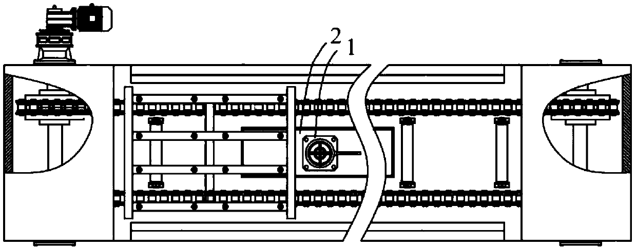
[0021] A. Add induction device 1 and adjustment device 2 to the transmission equipment;
[0022] B. Adjust the adjusting device 2 to change the position of the sensing device 1, corresponding to the position of the conveying product;
[0023] C. Turn on the equipment transmission, the induction device 1 is connected to the equipment motor, and controls the equipment motor in real time by sensing the position of the product.
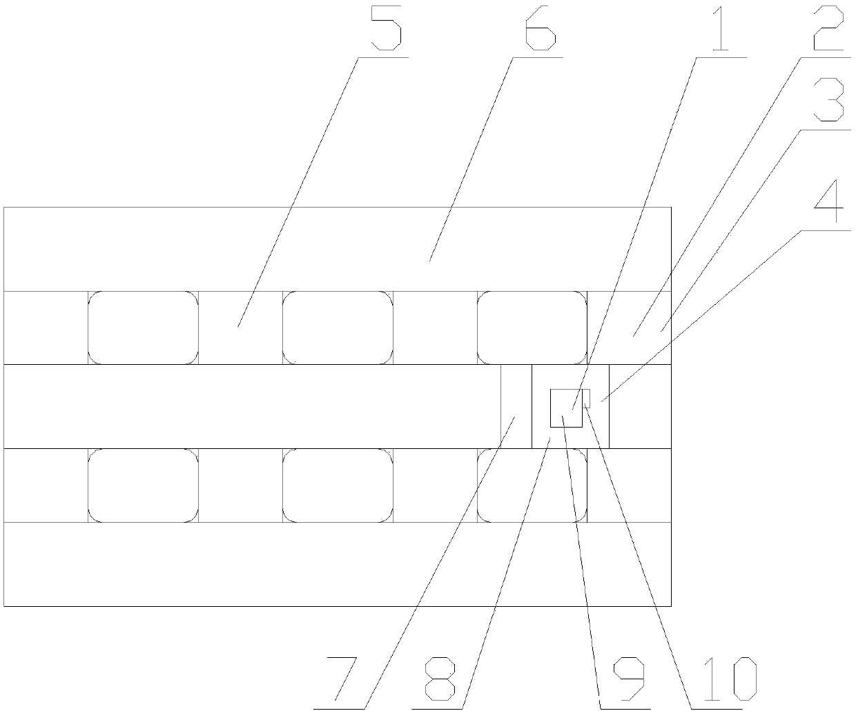
[0024] Further, the adjustment device 2 includes an adjustment track 3 and a moving slider 4; the adjustment track 3 is located on the transmission equipment, fixedly connected w...
PUM
 Abstract
Description
Claims
Application Information
PatSnap Eureka turns technology decisions into work you can execute. Powered by our Innovation Knowledge Graph, it runs expert workflows across engineering, life sciences, materials and intellectual property. Get your review-ready output in minutes.


