
Electric warming floor

A floor and electric heating technology, applied in the direction of electric heating system, heating method, lighting and heating equipment, etc., can solve the problems of separate control of inconvenient areas, inability to realize personalized layout, inconvenient temperature adjustment, etc.

Inactive Publication Date: 2018-02-02
GUANGZHOU NUANYILE HEAT ENERGY TECH CO LTD
View PDF8 Cites 0 Cited by
  • Summary
  • Abstract
  • Description
  • Claims
  • Application Information

AI Technical Summary

Problems solved by technology

According to the existing technology, this heating method is inconvenient for individual control of the area, cannot realize individualized layout, and is inconvenient to adjust the temperature, has poor flexibility, is difficult to achieve energy saving, and has environmental pollution problems, and the equipment is relatively complicated and the investment is large. Occasions, especially in situations where energy sources such as coal, oil, and gas are scarce, it is difficult to implement

Method used


Image

  • Electric warming floor
  • Electric warming floor

Examples


Embodiment Construction

[0024] The present invention will be further described below in conjunction with the accompanying drawings and specific embodiments.

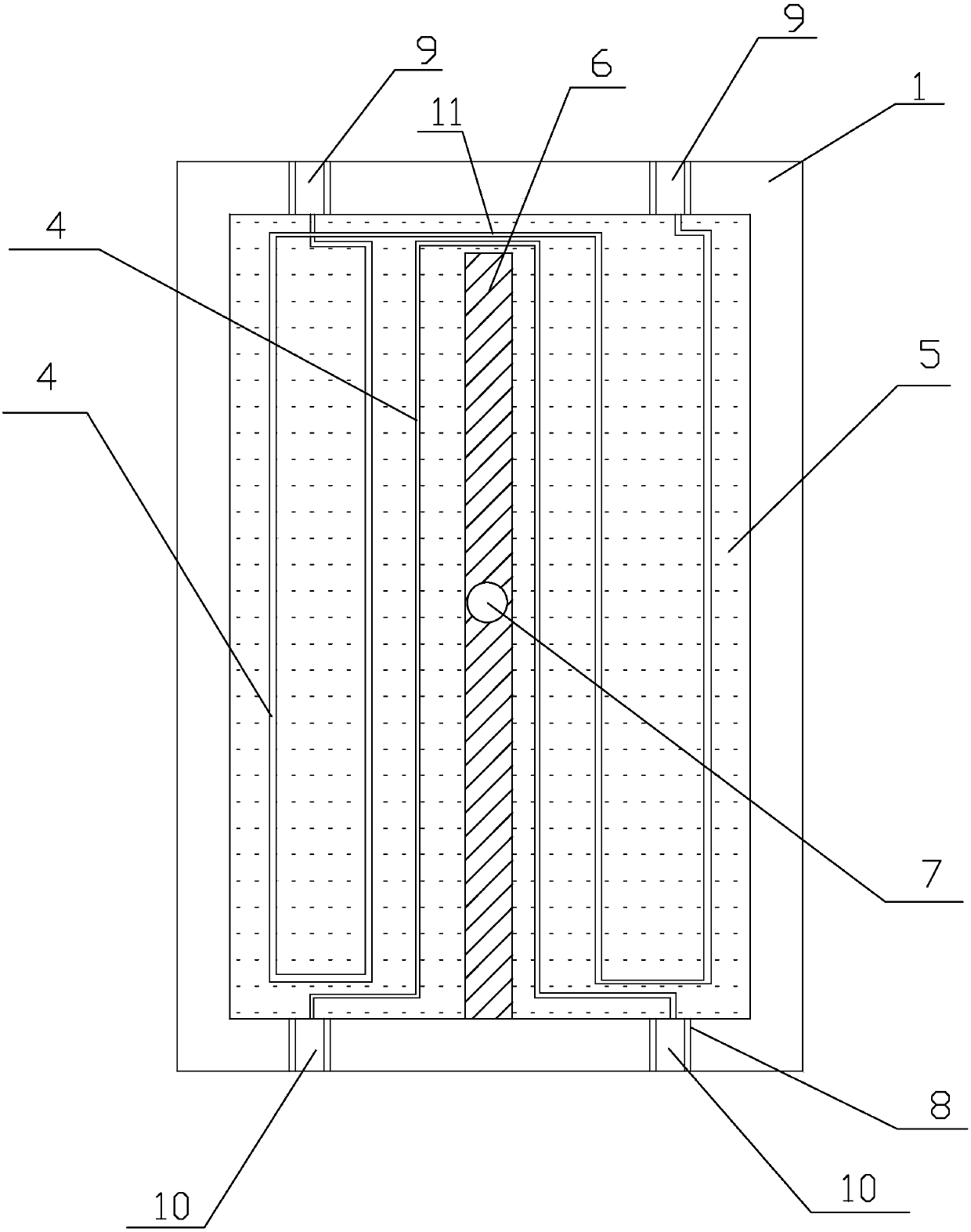
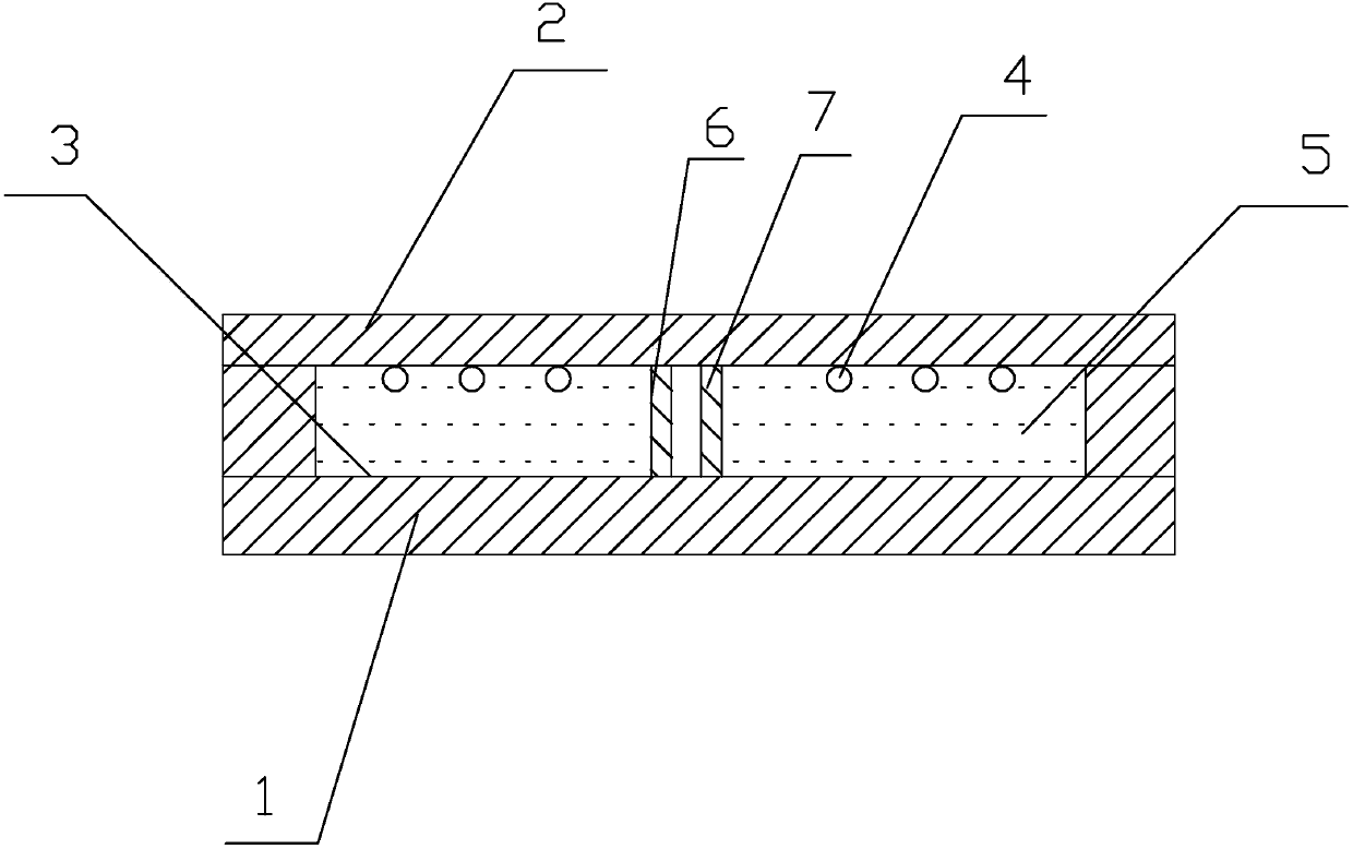
[0025] As shown in the figure, the present invention provides an electric heating floor, including an insulating base plate 1 and an insulating cover plate 2, the insulating cover plate 2 is fixed on the insulating base plate 1, and the upper surface of the insulating base plate 1 is provided with at least two A groove 3, the groove 3 is distributed on both sides of the upper surface of the insulating base plate 1, the heating wire 4 and the foaming agent 5 are arranged in the groove 3, and the foaming agent 5 is filled in the groove In the groove 3, the insulating bottom plate 1 is also provided with a rib plate 6, the rib plate 6 is located in the middle of the insulating base plate 1, the heating wire 4 is located in the foaming agent 5, and the foaming agent 5 Cured in the groove 3, the advantage of the present invention is that the groove ...


PUM

PropertyMeasurementUnit
Lengthaaaaaaaaaa

Abstract

The invention discloses an electric warming floor. The electric warming floor comprises an insulation bottom plate and an insulation cover plate. The insulation cover plate is fixed on the insulationbottom plate. At least two grooves are formed in the upper surface of the insulation bottom plate. The grooves are distributed on the two sides of the upper surface of the insulation bottom plate. Each groove is internally provided with a hot wire and a foaming agent. The grooves are filled with the foaming agent. A rib plate is also arranged on the insulation bottom plate. The rib plate is located in the middle of the insulation bottom plate. The hot wire is located in the foaming agent. The foaming agent is solidified in the grooves. According to the electric warming floor, area individual control is facilitated, the temperature is convenient to adjust, the flexibility is good, and the cost is low.

Description

technical field [0001] The invention relates to heating equipment, in particular to an electric heating floor. Background technique [0002] The heating method is generally to use the heat energy generated by the combustion of coal, oil, gas and other fuels to heat the occasions that need to be kept warm through a heat exchanger. According to the existing technology, this heating method is inconvenient for individual control of the area, cannot realize individualized layout, and is inconvenient to adjust the temperature, has poor flexibility, is difficult to achieve energy saving, and has environmental pollution problems, and the equipment is relatively complicated and the investment is large. Occasions, especially the occasions where energy sources such as coal, oil, and gas are scarce are difficult to implement. Contents of the invention [0003] The technical problem to be solved by the present invention is to overcome the above defects of the prior art, and provide an...

Claims


Application Information

Patent Timeline
IPC IPC(8): E04F15/02F24D13/02
CPCE04F15/02F24D13/024
Inventor 曾世锋
Owner GUANGZHOU NUANYILE HEAT ENERGY TECH CO LTD
Learn More