
Hardware connecting rod capable of being used for electric telescopic door

An electric telescopic and connecting rod technology, which is applied in door/window fittings, power control mechanisms, wing leaf control mechanisms, etc., can solve problems such as easy deformation, easy damage, unreasonable hardware connecting rod structure, etc., and achieve adhesion resistance dirt, strong adhesion effect

Inactive Publication Date: 2018-02-02
泰州亚东链条有限公司
View PDF0 Cites 0 Cited by
  • Summary
  • Abstract
  • Description
  • Claims
  • Application Information

AI Technical Summary

Problems solved by technology

[0002] At present, the electric telescopic doors used in the fields of enterprises, governments, villas, etc. are basically assembled into various structures through hardware connecting rods, and then the electric telescopic doors are opened and closed through the main shaft on the hardware connecting rods. However, due to the unreasonable structure of this kind of hardware connecting rod, the service life of the electric telescopic door is greatly reduced. This structure is easily damaged. In addition, the shaft sleeve on the metal connecting rod is also directly welded. This structure leads to poor stability of the metal connecting rod and is easy to deform. , if the hardware fastener is welded by multiple hardware parts, it will increase the difficulty of processing and manufacturing, especially for the current situation of high domestic raw material and labor prices, such defects are particularly prominent, and the metal connecting rod is easy to be corroded

Method used

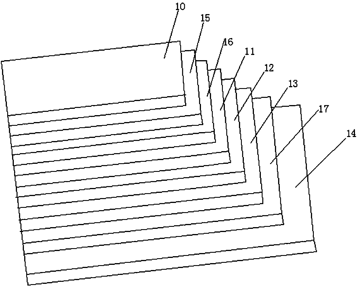

Image

  • Hardware connecting rod capable of being used for electric telescopic door
  • Hardware connecting rod capable of being used for electric telescopic door
  • Hardware connecting rod capable of being used for electric telescopic door

Examples


Embodiment Construction

[0015] The following will clearly and completely describe the technical solutions in the embodiments of the present invention with reference to the accompanying drawings in the embodiments of the present invention. Obviously, the described embodiments are only some, not all, embodiments of the present invention. Based on the embodiments of the present invention, all other embodiments obtained by persons of ordinary skill in the art without making creative efforts belong to the protection scope of the present invention.

[0016] see Figure 1-3 , the present invention provides a technical solution:

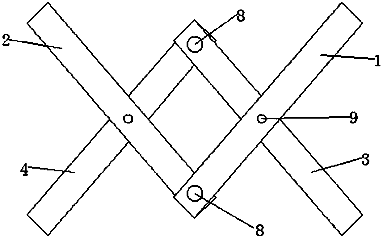
[0017] A metal connecting rod that can be used for electric telescopic doors, the hardware connecting rod includes connecting rod one 1, connecting rod two 2, connecting rod three 3 and connecting rod four 4, the connecting rod one 1 and connecting rod two 2 Wherein one end is vertically symmetrical structure, and described connecting rod three 3 and connecting rod four 4 also are...


PUM


Abstract

The invention discloses a hardware connecting rod capable of being used for an electric telescopic door. One end of a connecting rod I of the hardware connecting rod and one end of a connecting rod IIof the hardware connecting rod are of vertical symmetrical structures; a connecting rod III and a connecting rod IV are also of vertical symmetrical structures; a groove is formed in one end of the connecting rod I; through holes I are formed in positions, extending to the outer end surface of the connecting rod I, at the two ends of the groove; one end of the connecting rod II is blocked into the groove, and a through hole II is formed in the end part of the connecting rod II; a rotary shaft sequentially passes through the through holes I and the through hole II; the connecting rod I and theconnecting rod II are rotatably connected through the through holes I, the through hole II and a rotary shaft; the connecting rod III and the connecting rod IV are movably connected through same mechanisms adopted by the connecting rod I and the connecting rod II; the middle part of the connecting rod II clings to the middle part of the connecting rod IV, and the clung parts are equipped with pinrolls; and an anti-corrosion coating is coated on the surface of the hardware connecting rod. The hardware connecting rod easily opens the telescopic door, and enables the telescopic door to be resistant to corrosion.

Description

technical field [0001] The invention relates to the technical field of electric telescopic doors, in particular to a hardware connecting rod that can be used for electric telescopic doors. Background technique [0002] At present, the electric telescopic doors used in the fields of enterprises, governments, villas, etc. are basically assembled into various structures through hardware connecting rods, and then the electric telescopic doors are opened and closed through the main shaft on the hardware connecting rods. However, due to the unreasonable structure of this hardware connecting rod, the service life of the electric telescopic door is greatly reduced. Specifically, the hardware connecting rod is mainly assembled by hardware fasteners, and hardware fasteners are often assembled through multiple Such a structure is easily damaged, and the shaft sleeve on the metal connecting rod is also directly welded. This structure leads to poor stability of the metal connecting rod a...

Claims


Application Information

Patent Timeline
Patent Type & Authority Applications(China)
IPC IPC(8): E05F15/60
CPCE05F15/60E05Y2201/686E05Y2900/132
Inventor 刘志勇季亚东
Owner 泰州亚东链条有限公司
Learn More