A kind of H-shaped reinforced cutout structure and cutout method

An I-shaped and cutting hole technology, applied in blasting and other directions, can solve the problems of increased blasting resistance and insufficient blasting power

Active Publication Date: 2020-01-07
CHENGDU UNIV
View PDF12 Cites 0 Cited by
  • Summary
  • Abstract
  • Description
  • Claims
  • Application Information

AI Technical Summary

Problems solved by technology

[0003] The invention provides an I-shaped reinforced cutout structure and cutout method, which solves the problem that the conventional reinforced cutout hole is used in the prior art, and the explosive power is not enough to explode the rock between the cutout holes, resulting in increased blasting resistance. question

Method used


Image

  • A kind of H-shaped reinforced cutout structure and cutout method

Examples


Embodiment Construction

[0015] In order to make the above objects, features and advantages of the present invention more comprehensible, the present invention will be further described in detail below in conjunction with the accompanying drawings and specific embodiments.

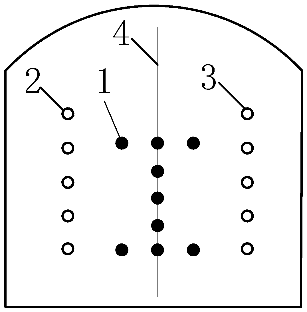
[0016] The embodiment of the present invention provides an I-shaped reinforced cut structure, such as figure 1 As shown, it includes the blastholes distributed on the blasting network, the blastholes include the central cutout 1, the left cutout 2 and the right cutout 3, and the middle cutout 1 is evenly distributed on the tunnel face The center line 4, the left cut hole 2 is set on the left side of the center line 4, the right cut hole 3 is set on the right side of the center line 4, and the middle cut hole 1 is an I-shaped Type reinforced cutout eye.

[0017] Among them, the central cutout 1 is 9 I-shaped reinforced cutouts, and the I-shaped reinforced cutout is an I-shaped distribution symmetrical to the center line 4; the lef...


PUM


Abstract

The invention relates to the technical field of tunnel rock mass tunneling blasting engineering and discloses an I-shaped reinforcing underholing structure and an underholing method. The I-shaped reinforcing underholing structure comprises blastholes distributed in a blasting network, wherein the blastholes comprise middle underholing holes (1), left underholing holes (2) and right underholing holes (3), wherein the middle underholing holes (1) are uniformly formed in the central line (4) of a tunnel face; the left underholing holes (2) are formed in the left side of the central line (4); theright underholing holes (3) are formed in the right side of the central line (4); and the middle underholing holes (1) are I-shaped reinforcing underholing holes. For tunnel blasting tunneling, the I-shaped reinforcing underholing structure can obtain an ideal blasting effect when the space between two adjacent underholing holes is excessively large, can reduce the influence caused by excessivelylarge space between two adjacent underholing holes, and provides engineering reference for rapid tunneling of a lithological tunnel of the same type.

Description

technical field [0001] The invention relates to the technical field of tunnel rock mass excavation and blasting engineering, in particular to an I-shaped reinforced cutting structure and a cutting method. Background technique [0002] In the excavation of tunnel guns, the structure of ordinary reinforced cutting holes is simple and easy to operate on site, but this kind of cutting structure has good blasting effect when the distance between the cutting holes is not large, and the explosion power is enough to blast the cutting holes The rocks between the holes, and when the distance between the holes is large, the explosion power is not enough to blast the rocks between the holes, and when the distance between the holes is large, the blasting force is not enough to blast the rocks between the holes, which will increase the blasting resistance and affect the rear centerline ( 20) The blasting effect of the cut hole on the left side and the cut hole on the right side of the cen...

Claims


Application Information

Patent Timeline
Patent Type & Authority Patents(China)
IPC IPC(8): F42D1/00F42D3/04
CPCF42D1/00F42D3/04
Inventor 谢飞鸿吴杰周杰余禹江
Owner CHENGDU UNIV
Why Eureka
Try Eureka