
Settlement monitoring mechanism and settlement monitoring method of building structure

A settlement monitoring and building structure technology, applied in measuring devices, mapping and navigation, height/level measurement, etc., can solve the problems of inability to real-time monitoring and low monitoring accuracy, and achieve the effect of improving the safety factor of use and preventing collapse accidents.

Inactive Publication Date: 2018-02-02
胡仲春
View PDF0 Cites 4 Cited by
  • Summary
  • Abstract
  • Description
  • Claims
  • Application Information

AI Technical Summary

Problems solved by technology

[0003] The main purpose of the present invention is to provide a settlement monitoring mechanism and a settlement monitoring method for building structures to solve the problems in the prior art that the settlement monitoring accuracy of building structures is low and cannot be monitored in real time

Method used


Image

  • Settlement monitoring mechanism and settlement monitoring method of building structure
  • Settlement monitoring mechanism and settlement monitoring method of building structure
  • Settlement monitoring mechanism and settlement monitoring method of building structure

Examples


Embodiment 1

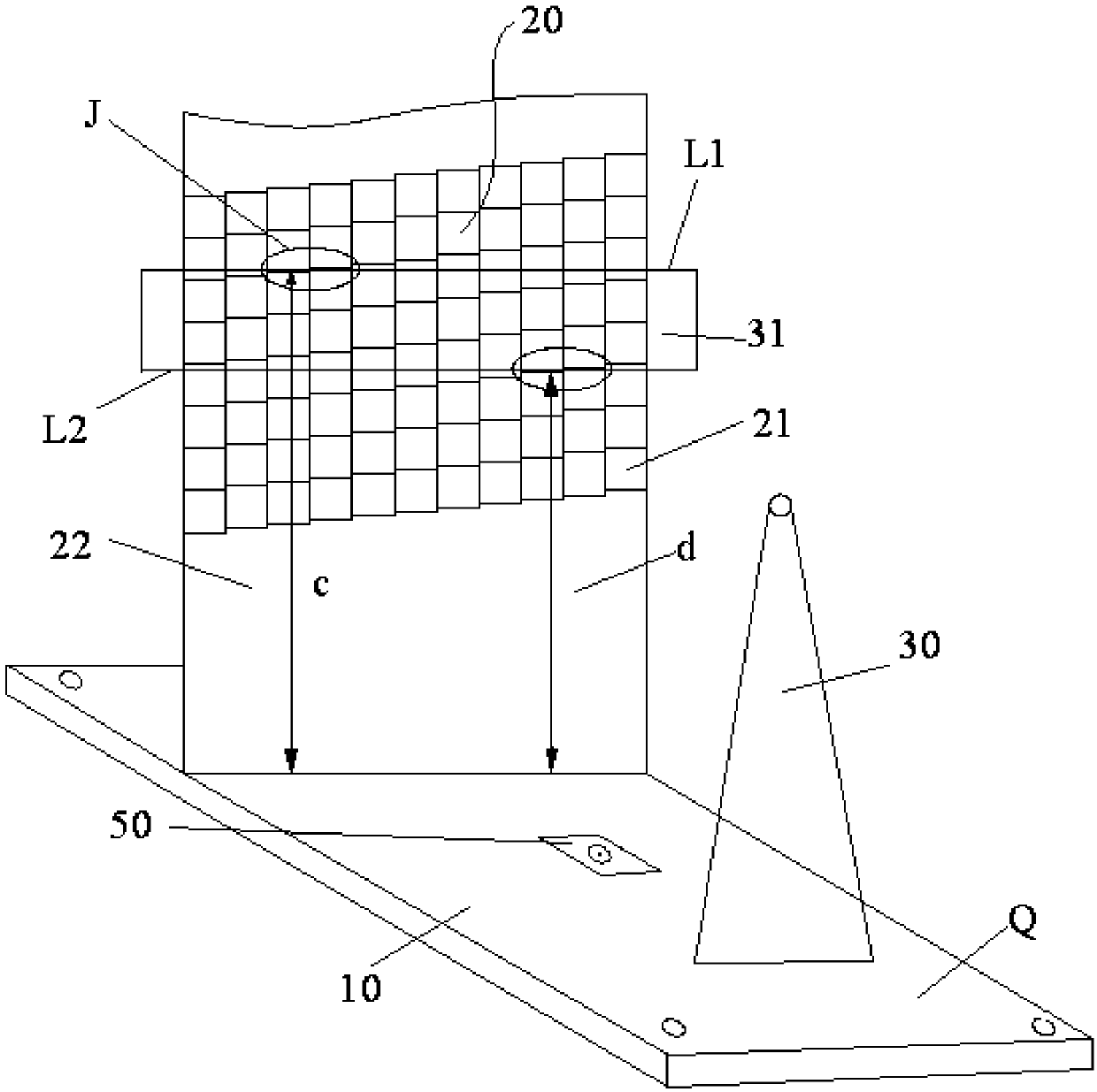
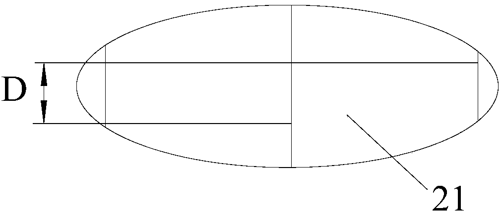
[0036] Such as figure 1 As shown, the settlement monitoring mechanism of Embodiment 1 includes a base 10 , a photoresistor assembly 20 and a laser emitter 30 . Wherein, the base 10 is set on the object to be monitored. The photoresistor assembly 20 is connected with the signal acquisition instrument and arranged on the base 10 . The photoresistor assembly 20 includes a plurality of photoresistors 21, and the plurality of photoresistors 21 are arranged in sequence along the vertical direction and the horizontal direction respectively. The laser emitter 30 is disposed on the base 10 .

[0037] The base 10 of the settlement monitoring mechanism is installed on the monitored piece. During the settlement monitoring process of the monitored piece by the settlement monitoring mechanism, the settlement of the photosensitive resistor assembly 20 is consistent with the settlement of the monitored piece. The laser transmitter 30 The position of the light beam 31 emitted on the photore...

Embodiment 2

[0067] The difference between the settlement monitoring mechanism in the second embodiment and the first embodiment is that the location of the laser emitter 30 is different.

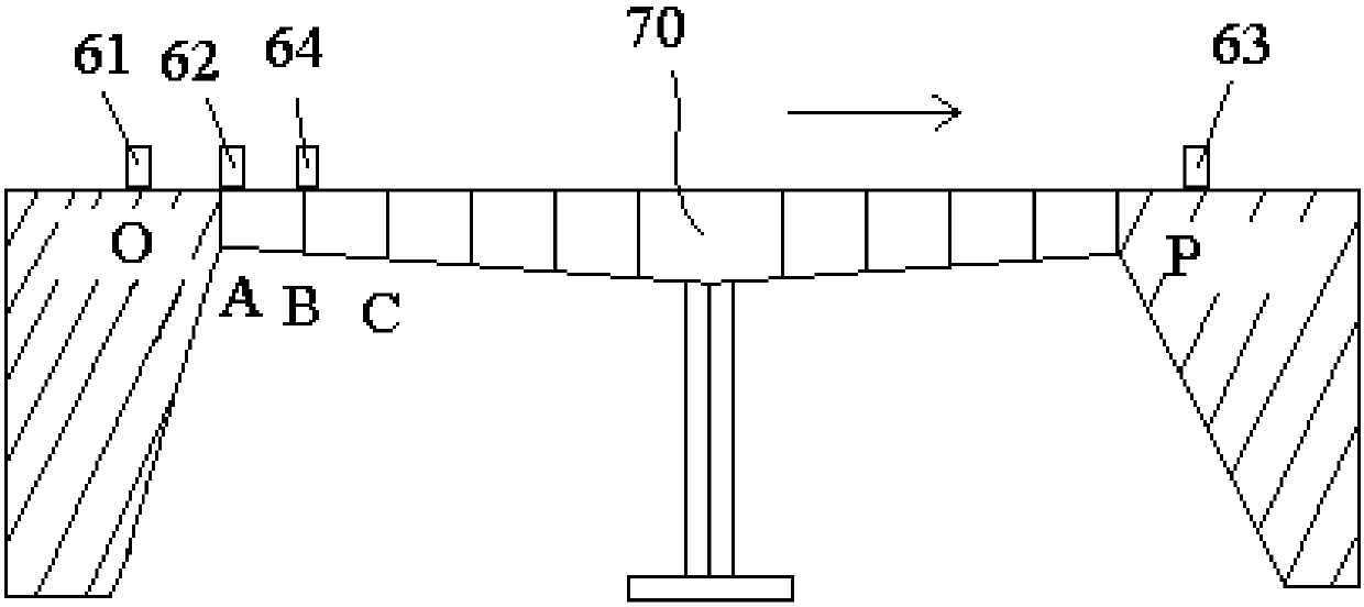
[0068] Such as Figure 4 and Figure 5 As shown, the laser emitter 30 in the second embodiment is arranged on the reference plane 40 . In this way, each laser emitter 30 corresponds to one photoresistor assembly 20 to emit light beams 31 , thereby making the structural layout of the settlement monitoring mechanism more reasonable and orderly, and making the settlement monitoring of the bridge 70 by the settlement monitoring mechanism more accurate.

[0069] Embodiment 2 also provides a settlement monitoring method of a building structure, using the above-mentioned settlement monitoring mechanism to monitor the building structure, wherein the settlement monitoring method includes:

[0070] Step S1: Install the laser emitters 30 of multiple settlement monitoring mechanisms on the reference plane 40, the...


PUM


Abstract

The invention provides a settlement monitoring mechanism and a settlement monitoring method of a building structure. Among them, the settlement monitoring mechanism includes: a base, which is arranged on the monitored piece; a photoresistor assembly connected to the signal acquisition instrument, which is arranged on the base, and the photoresistor assembly includes a plurality of photoresistors, and the plurality of photoresistors are respectively along the The vertical direction and the horizontal direction are arranged in sequence; the laser emitter is arranged on the base or the reference plane. The technical solution of the invention effectively solves the problems in the prior art that the settlement monitoring accuracy of building structures is low and cannot be monitored in real time.

Description

technical field [0001] The invention relates to the field of engineering construction, in particular to a settlement monitoring mechanism and a settlement monitoring method of a building structure. Background technique [0002] In the prior art, total stations, precision levels and leveling rods are mainly used for deflection and deformation monitoring of building structures (such as bridges and tunnels). However, the monitoring of the total station requires manual point-by-point monitoring, which is time-consuming and labor-intensive, and cannot be monitored in real time. At the same time, the monitoring accuracy is related to the operation of the staff, resulting in large measurement errors. If the leveling method is used to set steel nails on each beam slab as the observation point for deflection monitoring, and to periodically measure the measuring points buried in the beam slabs of each construction section, real-time monitoring of building structures (such as bridges) ...

Claims


Application Information

Patent Timeline
IPC IPC(8): G01C5/00
CPCG01C5/00
Inventor 胡仲春任高峰
Owner 胡仲春
Learn More