Button device and its balance bar structure

A balance bar and button technology, applied in the direction of contact operating mechanism, electrical components, electric switches, etc., can solve the problem of insufficient strength of the balance bar, achieve the best accuracy and improve the effect of sensitivity

Active Publication Date: 2019-11-05
LITE ON ELECTRONICS (GUANGZHOU) LTD +1
View PDF5 Cites 3 Cited by
  • Summary
  • Abstract
  • Description
  • Claims
  • Application Information

AI Technical Summary

Problems solved by technology

[0005] The technical problem to be solved by the present invention is to provide a key device and its balance bar structure, which can reinforce the problem of insufficient strength of the existing balance bar, so that the key cap will not be turned over during the action process, and the sensitivity of key triggering can be improved , and the cooperation between the balance bar and the keycap or bottom plate has better accuracy, and it can also have a sound-absorbing effect

Method used


Image

  • Button device and its balance bar structure
  • Button device and its balance bar structure
  • Button device and its balance bar structure

Examples


no. 1 example

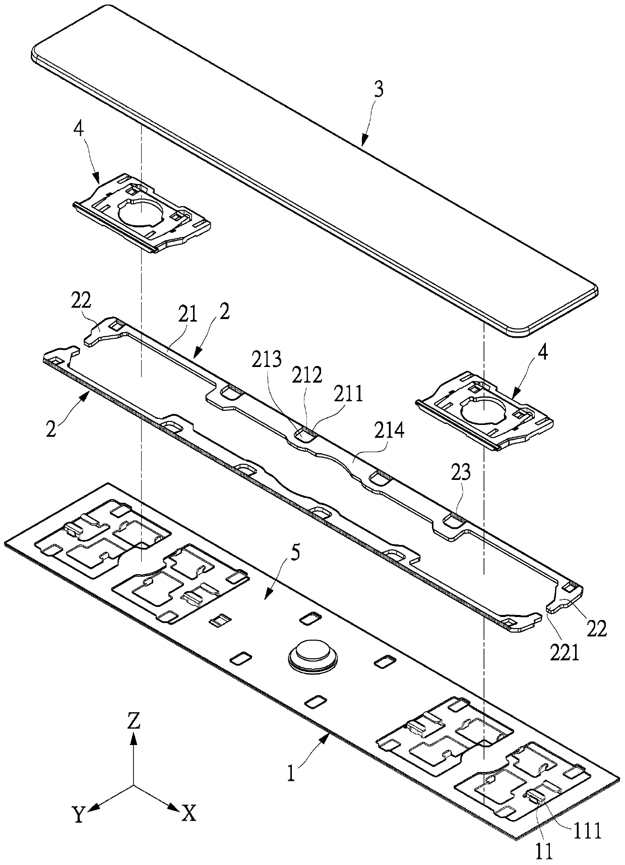
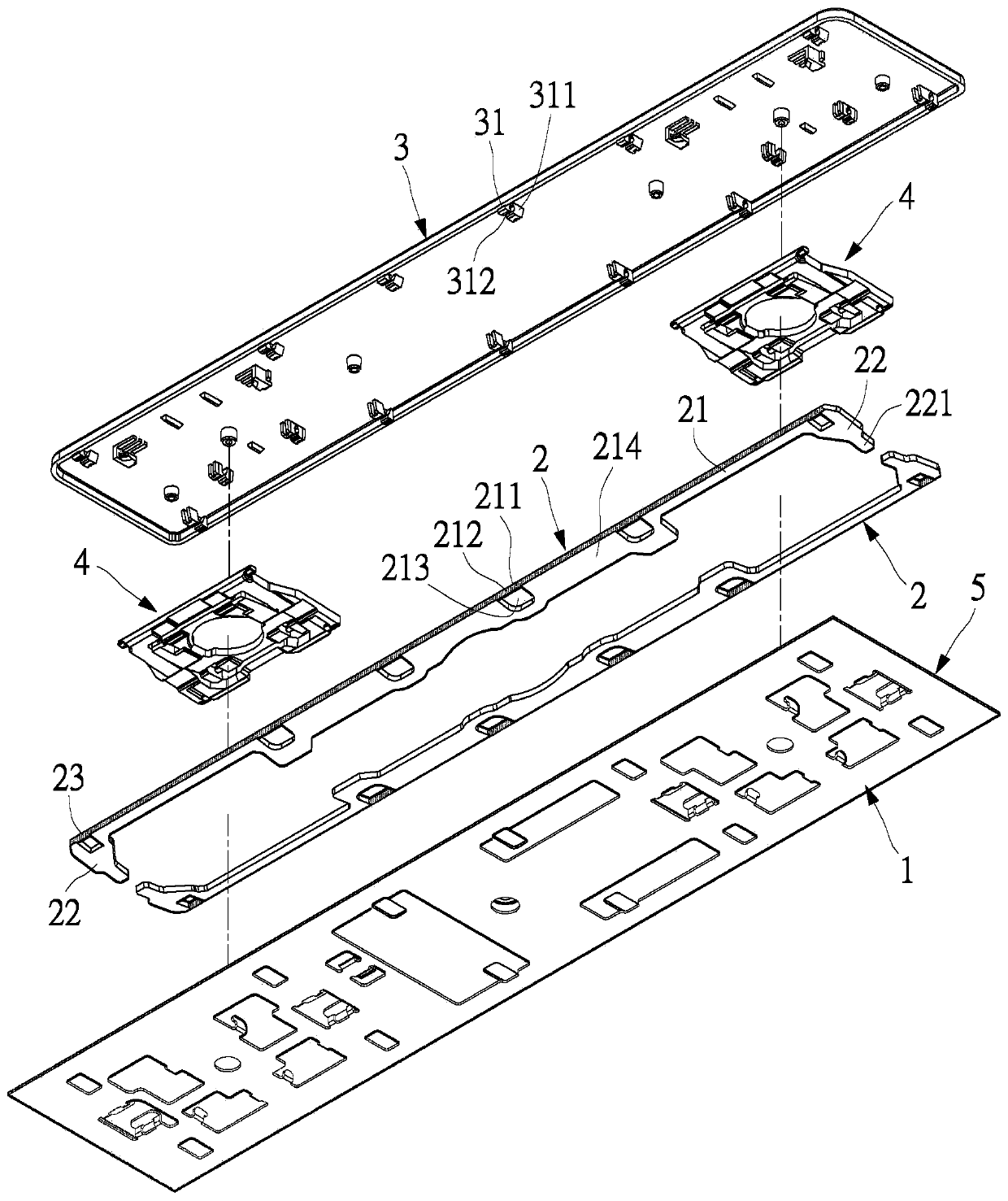
[0018] see figure 1 and figure 2 , the present invention provides a key device, which can be applied to multiple keys or other keys, and the key device includes a bottom plate 1 , at least one balance bar 2 and a key cap 3 .

[0019] The bottom plate 1 can be made of metal plate or other suitable materials, and a scissors-type assembly 4 can be further provided between the bottom plate 1 and the keycap 3, which is a double-link parallel mechanism, and can be used to guide the keycap 3 to be put on. , down, and balance the user's force on each key. A conductive film 5 may be disposed on the bottom plate 1 . In the drawings disclosed in this embodiment, the bottom plate 1 and the conductive film 5 are shown as a single body. In fact, a keyboard can have multiple key devices, and the bottom plates 1 of the multiple key devices are connected as one. It is also connected as one.

[0020] One or two balance poles 2 can be provided. In this embodiment, two balance poles 2 are di...

no. 2 example

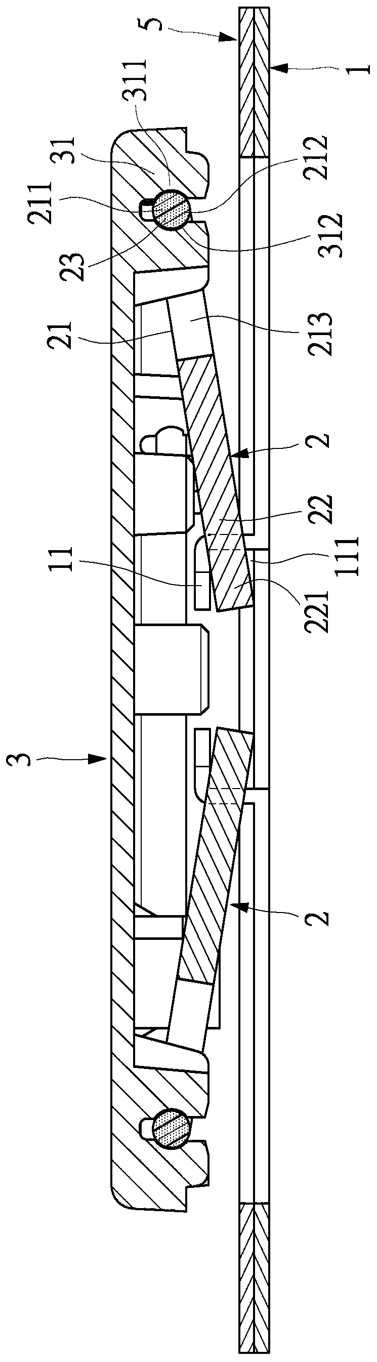
[0027] see Figure 4 and Figure 5 The main difference between this embodiment and the first embodiment is that in this embodiment, the plastic material 23 is formed on the first sliding joint 221, and the plastic material 23 can be formed on the entire first sliding joint 221, or only on the first sliding joint 221. Part (for example, the surface) of the first sliding portion 221 . The structure and actions of this embodiment are substantially the same as those of the first embodiment, and will not be repeated here.

[0028]The balance bar of the present invention adopts a plate-shaped design, which can replace the existing balance bar with a circular section, and obtain the advantage of plate-shaped geometric strength. A balance bar with a thinner thickness can reach the design strength of the existing balance bar to achieve space constraints. In this way, the optimized design of the pressing feel at the four corners of the button device is effectively achieved with geomet...


PUM


Abstract

The invention discloses a key device, which comprises a bottom plate, a keycap and at least one balance bar, wherein each balance bar is a tabular body and arranged between the bottom plate and the keycap; and each balance bar is provided with a top plate and two side plates, the top plate and the side plates are made of a metal material, two side plates are connected with two ends of the top plate, one end, far away from the top plate, of each of the two side plates is connected to the bottom plate and the top plate is connected to the keycap. A plastic material is formed on at least one of the top plate and the two side plates of each balance bar, a composite structure is formed by each balance bar, and each balance bar is in contact with at least one of the keycap and the bottom plate through the corresponding plastic material. Therefore, insufficient strength of an existing balance bar can be reinforced; and coordination of the balance bars and the keycap and the bottom plate has relatively good accuracy, is not too loose or too tight and also has a silencing effect.

Description

technical field [0001] The invention relates to a key device and its balance bar structure, in particular to a balance bar structure applied to a key device or other input devices. Background technique [0002] On the existing computer keyboards, multiple keys or function keys with a large ratio of length to width will be designed with a balance bar. The balance bar is made of a metal material with a circular cross-section. The other end of the balance bar is slidably arranged on the bottom plate, thereby forming a balance mechanism. When the key is pressed, the balance mechanism can be used to keep the keycap horizontal relative to the bottom plate during the action by sliding the balance bar relative to the bottom plate and pivoting relative to the keycap, thereby preventing the keycap from turning over during the action, so that Reduce the sensitivity of key triggers. [0003] Due to the current trend of the notebook market, the total height of the keyboard is getting l...

Claims


Application Information

Patent Timeline
Patent Type & Authority Patents(China)
IPC IPC(8): H01H3/12H01H13/20H01H13/705
CPCH01H3/125H01H13/20H01H13/705
Inventor 颜铭甫
Owner LITE ON ELECTRONICS (GUANGZHOU) LTD
Why Eureka
Try Eureka