Telephone receiver acoustic testing device and telephone receiver acoustic testing system

A technology of acoustic testing and receivers, applied in the direction of electrical components, etc., can solve problems such as large measurement errors, hidden dangers of product quality, test distortion stability, etc., and achieve accurate sensitivity, accurate test results, and high test efficiency.

Active Publication Date: 2018-02-02
SHENZHEN EVERWIN PRECISION TECH
View PDF6 Cites 1 Cited by
  • Summary
  • Abstract
  • Description
  • Claims
  • Application Information

AI Technical Summary

Problems solved by technology

[0007] However, the receiver testing device of the prior art has a large measurement error due to purely manual testing.
In addition, the operator manually pushes the test needle of the device to realize the connection with the circuit terminal, which requires the operator to spend a long time to complete the work of aligning and confirming the establishment of the electrical connection, and the difference in the contact point of each test needle is likely to cause test distortion or poor stability
And the test and position adjustment are done by hand, which makes the production efficiency of the receiver low
Moreover, the existing receiver test does not adequately position the receiver. Since the test needle is easily deflected during the manual operation test, the receiver shell is scratched, and there are hidden dangers in product quality.

Method used


Image

  • Telephone receiver acoustic testing device and telephone receiver acoustic testing system
  • Telephone receiver acoustic testing device and telephone receiver acoustic testing system
  • Telephone receiver acoustic testing device and telephone receiver acoustic testing system

Examples


Embodiment 1

[0038] This embodiment provides an acoustic testing device for a receiver, including a driving device and an output device.

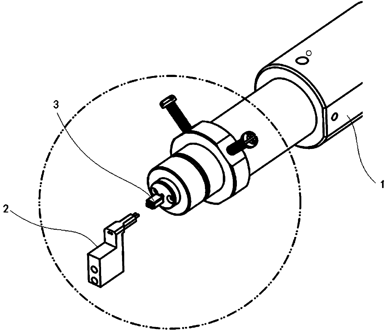
[0039] like Figure 4 As shown, the tested receiver 50 includes a pair of circuit terminals 52 and a sound tube 54 protruding from the shell.

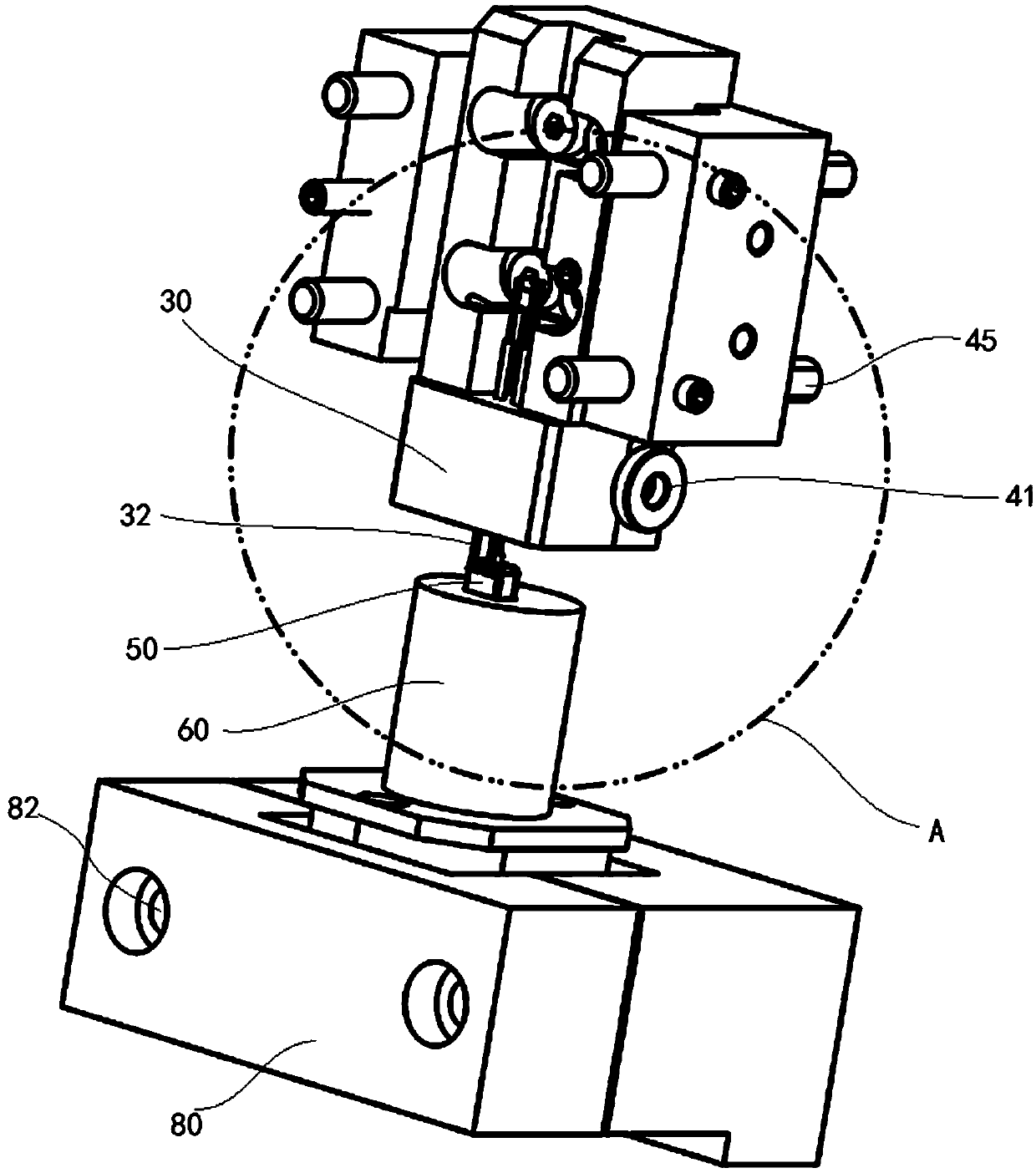
[0040] Please refer to 2 and Figure 5 , the driving device includes a bracket 10, a guide rail 12, a pressing assembly and a test adjustment device. In this embodiment, the guide rail 12 is installed vertically on the bracket 10 . Vertical rails are arranged on the bracket 10, and the guide rails 12 are slidably installed on the vertical rails.

[0041]The lower end of the guide rail 12 is fixed with a pressing component for inputting test signals. The pressing component adjusts the docking position of the receiver under test through the test adjusting device.

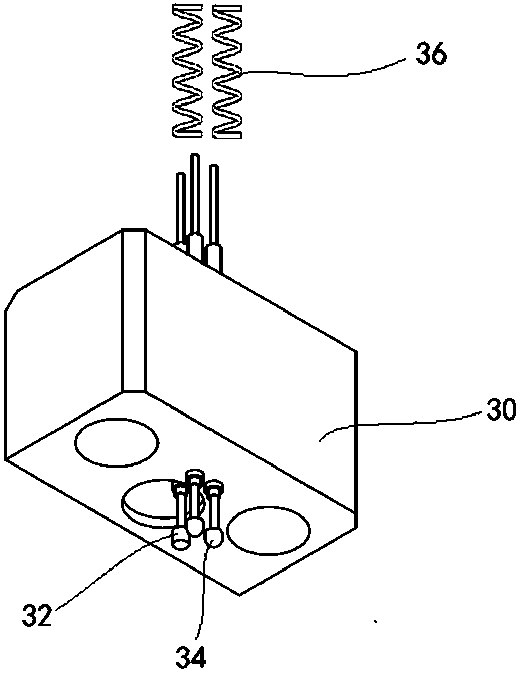
[0042] Please refer to image 3 , the pressing assembly includes a pressing head 30 fixed on the guide rail 12 , a positioning column 32 adjustab...

Embodiment 2

[0062] This embodiment relates to an acoustic test system using the receiver acoustic test device, including a test terminal and several test sensors.

[0063] The test terminal is connected to the drive cylinder of the receiver acoustic test device. The test terminal is connected to a position sensor disposed in the coupling cavity 64 close to the sealing ring 70 . One end of the test pin 34 of the receiver acoustic test device is connected to the signal input end of the test terminal, and the test sensor of the acoustic test system is arranged in the coupling cavity 64 or the extension coupling cavity 86 .


PUM


Abstract

The invention discloses a telephone receiver acoustic testing device and a telephone receiver acoustic testing system. The device comprises a driving device and an output device, the driving device comprises a bracket, a guide rail, a pressing component and a testing adjustment device, the guide rail is installed on the bracket, the pressing component used for inputting testing signals is fixed tothe guide rail, and the pressing component adjusts the abut joint position with a tested telephone receiver via the testing adjustment device; the output device comprises a testing seat, a locating cavity and a coupling cavity are formed in the testing seat, and a sealing ring is arranged between the locating cavity and the coupling cavity of the tested telephone receiver. The telephone receiveracoustic testing device and system can achieve automatic acoustic testing, the testing efficiency is higher, the test result is more accurate, and the product yield is improved.

Description

technical field [0001] The invention relates to the technical field of acoustic testing, in particular to a receiver acoustic testing device and an acoustic testing system. Background technique [0002] The existing receiver generally refers to the moving iron receiver, and its working principle is: the changing audio electric signal is fed into the voice coil, the voice coil is placed in the magnetic gap of a permanent magnet magnetic circuit, and the changing electromagnetic field force of the voice coil due to the changing current , that is, driven by the Lorentz force to vibrate up and down, and drive the diaphragm to drive the front and rear air to generate sound waves. [0003] Although there are many types of receivers with other transduction principles, the moving iron receiver has become the mainstream electroacoustic device for audio terminals in mobile phones and fixed phones because of its high cost performance, mature production technology, changing dimensions a...

Claims


Application Information

Patent Timeline
Patent Type & Authority Applications(China)
IPC IPC(8): H04R29/00
CPCH04R29/00
Inventor 魏旦丰
Owner SHENZHEN EVERWIN PRECISION TECH
Why Eureka
Try Eureka