A parking space detection method based on the layout of shooting equipment
A technology for photographing equipment and parking space detection, which is applied in traffic flow detection, indicating the direction of various open spaces in the parking lot, etc. It can solve the problems of low contribution of the intelligent parking system, low amount of information detected and fed back, and high system complexity, and achieve real-time Efficient monitoring, lower deployment costs, and good timeliness
- Summary
- Abstract
- Description
- Claims
- Application Information
AI Technical Summary
Problems solved by technology
Method used
Image
Examples
Embodiment 1
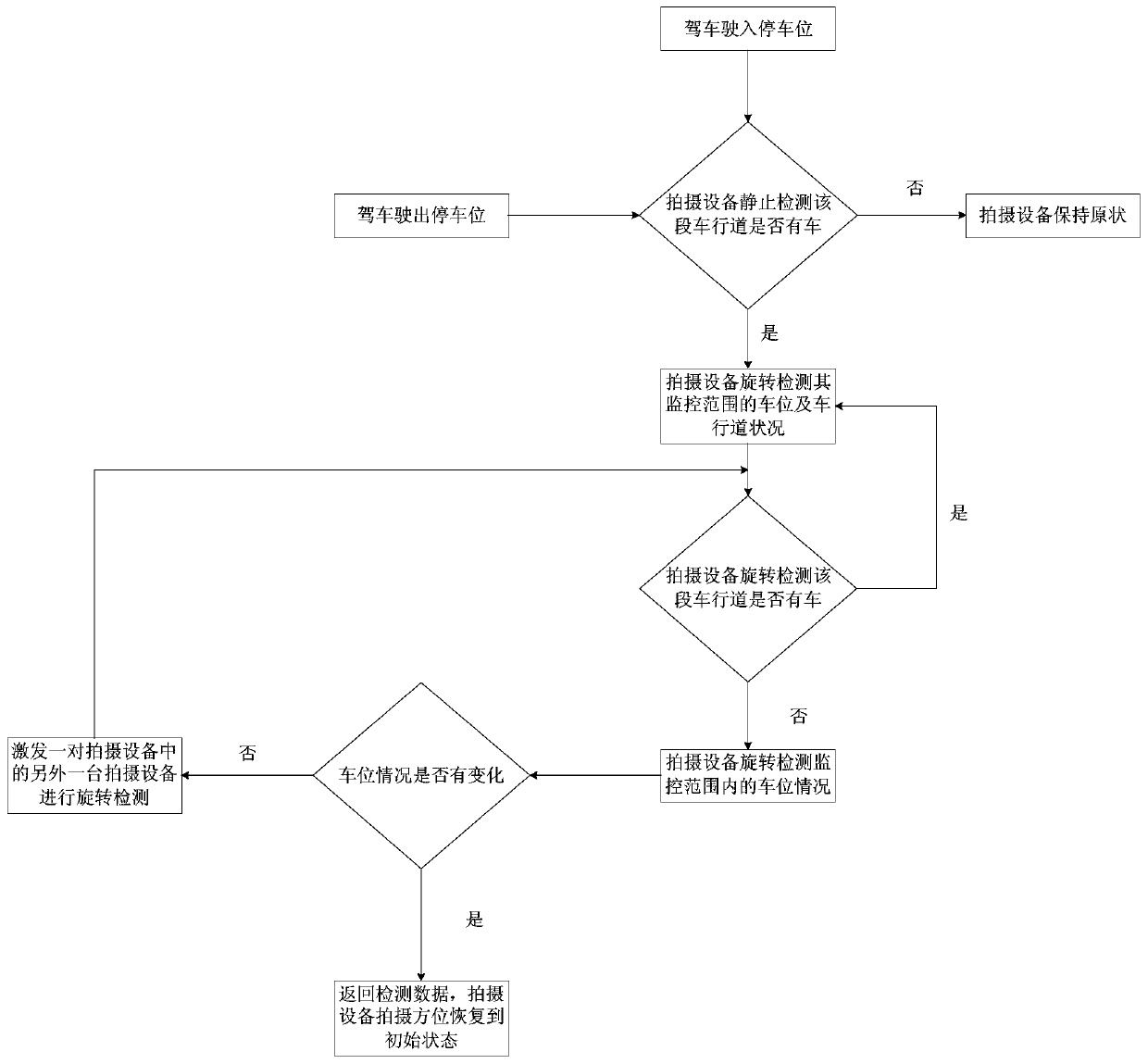
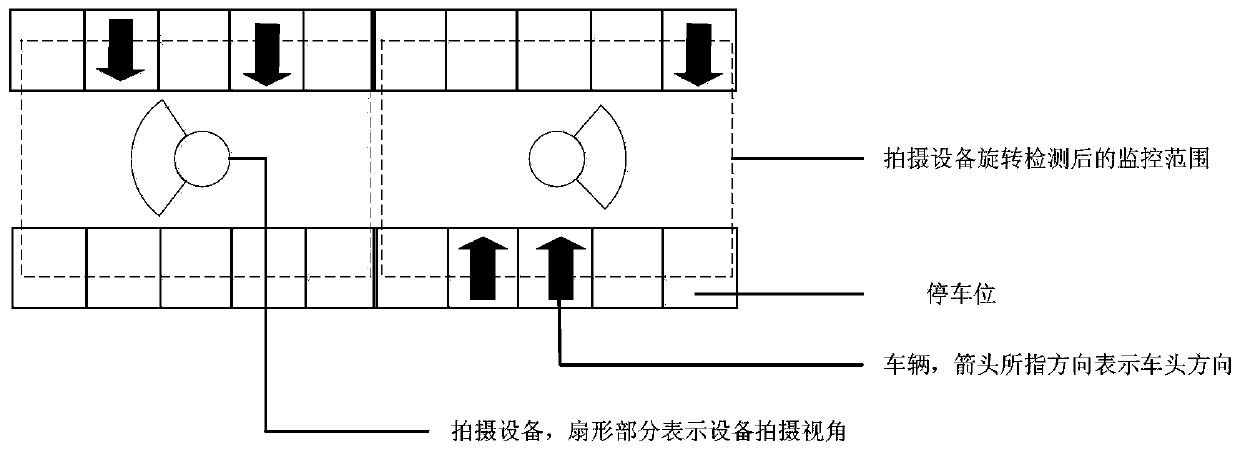
[0053] to combine Figure 4 In this example of the present invention, the vehicle enters the parking lot from the entrance, drives through the monitoring range of No. 1 equipment, and parks the car in the parking space within the monitoring range of No. 2 equipment. It can be seen that as soon as the vehicle enters the parking lot, it will be detected by the No. 1 device, and the No. 1 device will turn on the rotation detection to continuously detect the conditions of each parking space and the condition on the roadway within its monitoring range. When the vehicle leaves the monitoring range of No. 1 device, No. 1 device stops detection and returns the last detected data. Because No. 1 device first detects that there is a car and then detects that there is no car, it will trigger the adjacent traffic on the same lane. Device No. 2 rotation detection. When the vehicle leaves the monitoring range of No. 1 device, due to the initial orientation problem of No. 2 device, if No. 2 ...
Embodiment 2
[0056] to combine Figure 5 In this example of the present invention, the vehicle enters the parking lot from the entrance, drives through the monitoring range of No. 1 equipment, and parks the car in the parking space within the monitoring range of No. 5 equipment. It can be seen that as soon as the vehicle enters the parking lot, it will be detected by the No. 1 device, and the No. 1 device will turn on the rotation detection to continuously detect the conditions of each parking space and the condition on the roadway within its monitoring range. When the vehicle leaves the monitoring range of No. 1 device, No. 1 device stops detection and returns the last detected data. Because No. 1 device first detects that there is a car and then detects that there is no car, it will trigger the adjacent traffic on the same lane. Device No. 2 rotation detection. Similarly, No. 2 device triggers the rotation detection of No. 3 device, thus forming a chain in the combination to trigger the...
Embodiment 3
[0059] to combine Image 6 In this example of the present invention, the vehicle drives out of a parking space within the monitoring range of the No. 2 device, passes through the monitoring range of the No. 1 device, and finally drives out of the parking lot. Because in the combination of No. 1, No. 2, and No. 3 devices, the initial shooting position of the intermediate device, that is, No. 2 device, is not required, so at this time, the vehicle drives out of the monitoring area of No. 2 device and enters the monitoring area of No. 1 device. , may or may not be detected. like Figure three , the initial shooting position of No. 2 device will not detect the vehicle leaving, but when the vehicle appears within the monitoring range of No. 1 device, No. 1 device will rotate to detect the parking space it is responsible for. If there is no change in the parking space information, it will not return data. When the vehicle leaves the range of No. 1 device, No. 1 device will tr...
PUM
 Abstract
Description
Claims
Application Information
 - R&D
- Intellectual Property
- Life Sciences
- Materials
- Tech Scout
- Unparalleled Data Quality
- Higher Quality Content
- 60% Fewer Hallucinations
Browse by: Latest US Patents, China's latest patents, Technical Efficacy Thesaurus, Application Domain, Technology Topic, Popular Technical Reports.
© 2025 PatSnap. All rights reserved.Legal|Privacy policy|Modern Slavery Act Transparency Statement|Sitemap|About US| Contact US: help@patsnap.com


