
Valve device for a fuel injection system and fuel injection system

A technology of fuel injection system and valve device, which is applied in the direction of fuel injection device, special fuel injection device, charging system, etc.

Inactive Publication Date: 2018-02-06
CONTINENTAL AUTOMOTIVE GMBH
View PDF2 Cites 0 Cited by
  • Summary
  • Abstract
  • Description
  • Claims
  • Application Information

AI Technical Summary

Problems solved by technology

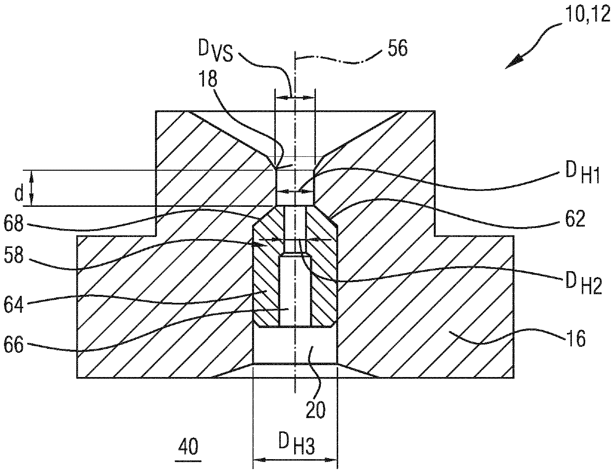
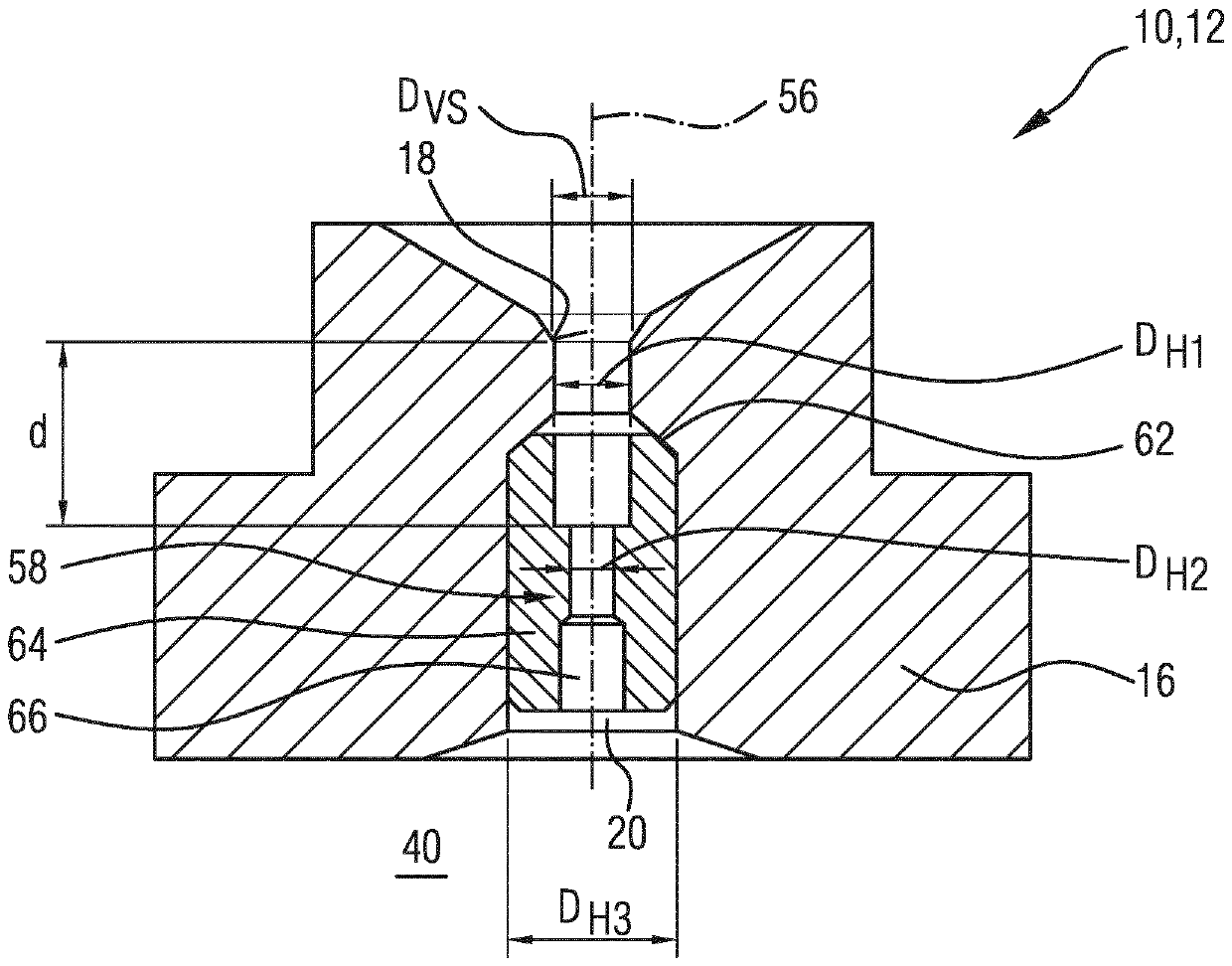
However, a flat opening pressure characteristic curve can only be used with a sufficiently large diameter D of the valve seat 18 VS to fulfill

Method used


Image

  • Valve device for a fuel injection system and fuel injection system
  • Valve device for a fuel injection system and fuel injection system
  • Valve device for a fuel injection system and fuel injection system

Examples


Embodiment Construction

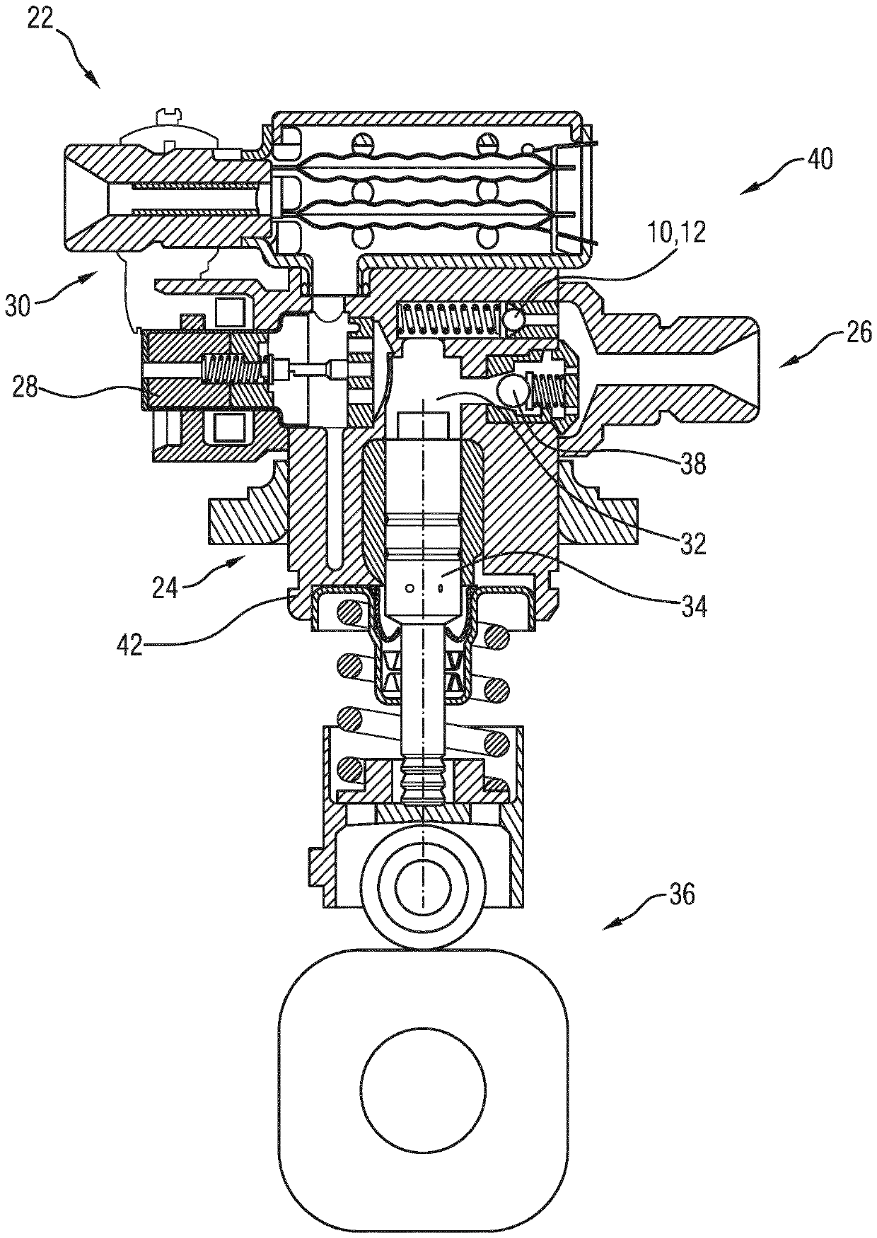
[0038] figure 1 A longitudinal section through a fuel injection system 22 is shown, via which fuel can be injected into at least one combustion chamber of the internal combustion engine. Fuel injection system 22 has a high pressure fuel pump 24 and a fuel storage area 26 .

[0039] Fuel is loaded at high pressure by a high-pressure fuel pump 24 , for example diesel at a pressure between 1500 and 3000 bar or gasoline at a pressure between 200 and 350 bar. For this purpose, fuel enters the pressure space 32 of the high-pressure fuel pump 24 from the low-pressure region 30 via the inlet valve 28 . The pump piston 34 , which is driven by the drive device 36 , moves in translation to and fro in the pressure space 32 and in the process reduces or increases the volume of the pressure space 32 . In this way, the fuel in the pressure space 32 is compressed and thus pressurized. After compression in the pressure space 32 , the fuel exits the pressure space 32 via an outlet valve 38 ...


PUM


Abstract

The invention relates to a valve device (10) for a fuel injection system (22), comprising a high-pressure feed bore (20) and a sealing element (14), which interacts with a valve seat (18), for openingand closing the high-pressure feed bore (20), wherein the high-pressure feed bore has a first diameter (DH1) adjacent to the valve seat (18) and a second diameter (DH2) at a distance from the valve seat (18), which second diameter is smaller than the first diameter (DH1) in order to form an orifice (48). The invention further relates to a fuel injection system (22) that comprises the valve device(10).

Description

technical field [0001] The invention relates to a valve arrangement for a fuel injection system which can be used in particular as a pressure limiting valve for depressurizing a high-pressure region of the fuel injection system. Furthermore, the invention relates to a fuel injection system having a valve arrangement of this type. Background technique [0002] A fuel injection system is used to inject fuel into at least one combustion chamber of an internal combustion engine, in which fuel injection system the fuel is first compressed to a high pressure in order to be able to comply with the requirements for predefined emission values ​​during injection. [0003] Here, diesel fuel is usually compressed to a pressure range of 1500 bar to 3000 bar and gasoline fuel is compressed to a pressure range of 200 bar to 350 bar. In order to protect certain elements in the fuel injection system, such as sensors or the so-called common rail, which is positioned downstream of the high-pr...

Claims


Application Information

Patent Timeline
IPC IPC(8): F02M63/00
CPCF02M63/005F02M2200/28F02M63/0005
Inventor L.范希梅L.阿佩尔斯K.弗莫伦
Owner CONTINENTAL AUTOMOTIVE GMBH
Learn More