Movable building waste treatment device

A technology for processing equipment and construction waste, applied in gas treatment, grain treatment, transportation and packaging, etc., can solve the problems of unreasonable crushing and treatment operation of construction waste, adverse impact on social environment, damage to people's personal health, etc. Easy to move, well-designed effect

Inactive Publication Date: 2018-02-09
宁波旅橙汽车科技有限公司
View PDF13 Cites 0 Cited by
  • Summary
  • Abstract
  • Description
  • Claims
  • Application Information

AI Technical Summary

Problems solved by technology

[0002] With the rapid development of the construction industry, a large amount of construction waste will inevitably be generated during the construction process. If these construction wastes are discarded directly, it will not only cause a waste of resources, but also have an adverse impact on the social environment. Therefore, It is necessary to use corresponding construction waste treatment devices to deal with these construction wastes; for existing construction waste treatment devices, limited by structural and design constraints, it is often not reasonable to be able to pulverize construction waste. , it is not possible to dry the buildings containing moisture, and sometimes it will cause a lot of dust, which will pollute the environment and cause damage to people's health.

Method used


Image

  • Movable building waste treatment device
  • Movable building waste treatment device
  • Movable building waste treatment device

Examples


Embodiment Construction

[0016] The technical solution of this patent will be further described in detail below in conjunction with specific embodiments.

[0017] Embodiments of the present patent are described in detail below, examples of which are shown in the drawings, wherein the same or similar reference numerals designate the same or similar elements or elements having the same or similar functions throughout. The embodiments described below by referring to the figures are exemplary and are only used for explaining the patent, and should not be construed as limiting the patent.

[0018] In the description of this patent, it is to be understood that the terms "center", "upper", "lower", "front", "rear", "left", "right", "vertical", "horizontal", The orientation or positional relationship indicated by "top", "bottom", "inner", "outer", etc. is based on the orientation or positional relationship shown in the drawings, and is only for the convenience of describing this patent and simplifying the des...


PUM


Abstract

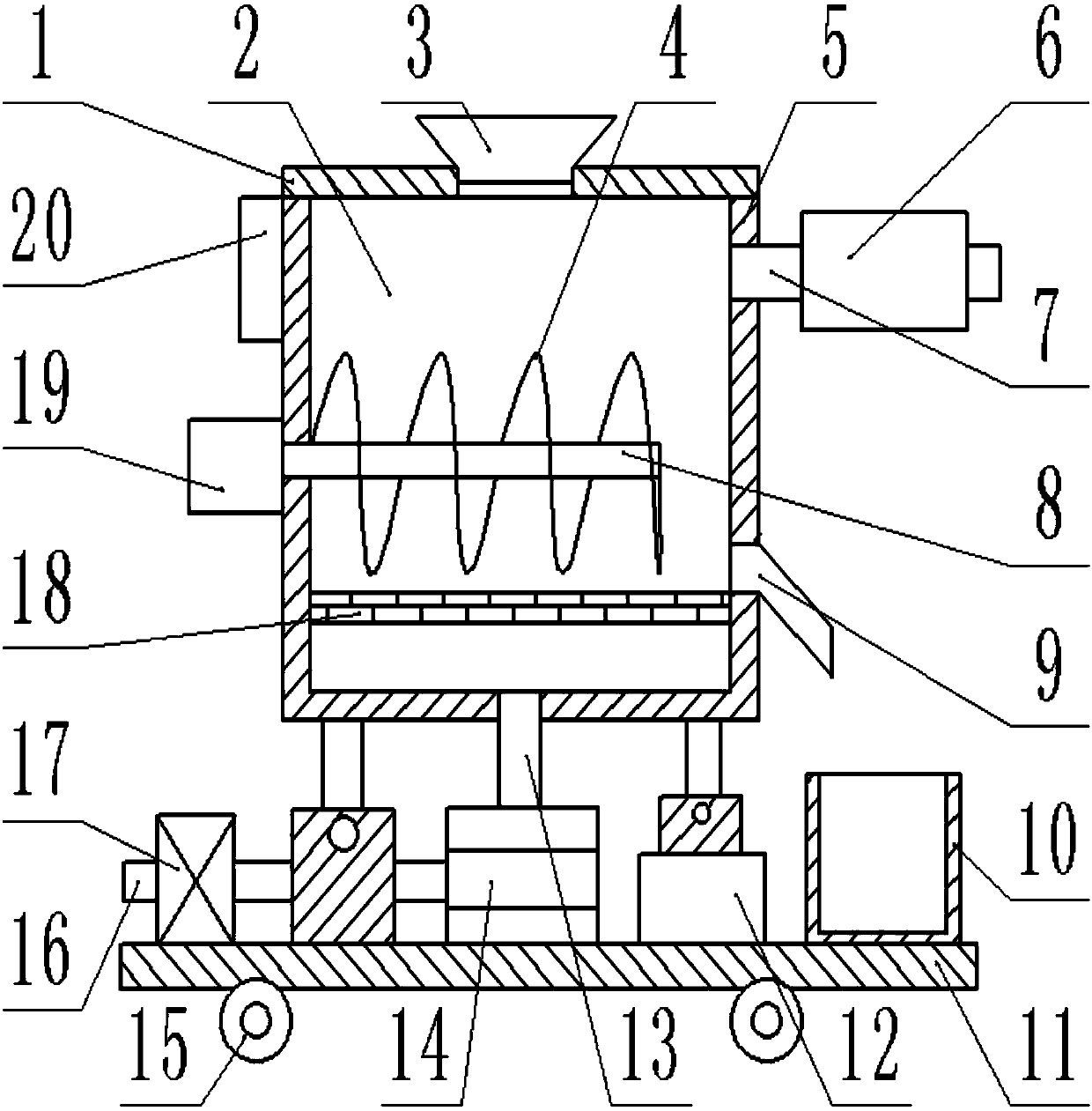
The invention provides a movable building waste treatment device, and belongs to the field of building waste treatment devices. The movable building waste treatment device comprises a housing, a filter device and a supporting device, wherein the housing is rectangular and is vertically arranged, and the upper end of the housing is equipped with an end cover; the end cover is in threaded connectionwith the housing; a charge device which is fixedly connected is arranged on the middle part of the end cover; a crushing cavity is arranged inside the housing; a rotary shaft is arranged above, and fixedly connected crushing blades are further arranged; the left end of the rotary shaft is equipped with a fixedly connected rotary motor; the rotary motor is arranged on the left surface of the housing; the left end and the right end of a heat conduction plate are fixedly connected on the inner surface of the housing separately; the right end of the heat conduction plate is equipped with a discharge tube which is fixedly connected to the housing; and the left end of the housing is equipped with a control device which is fixedly connected. The movable building waste treatment device is simplein structure, is reasonable in design, is practical and convenient, is convenient to move, can effectively treat waste sufficiently, and further can prevent an ambient environment from being polluted.

Description

technical field [0001] The invention relates to a construction waste treatment device, in particular to a movable construction waste treatment device. Background technique [0002] With the rapid development of the construction industry, a large amount of construction waste will inevitably be generated during the construction process. If these construction wastes are discarded directly, it will not only cause a waste of resources, but also have an adverse impact on the social environment. Therefore, It is necessary to use corresponding construction waste treatment devices to deal with these construction wastes; for existing construction waste treatment devices, limited by structural and design constraints, it is often not reasonable to be able to pulverize construction waste. Therefore, it is not possible to dry buildings containing moisture, which sometimes leads to a large amount of dust, which pollutes the environment and causes damage to people's health. Contents of th...

Claims


Application Information

Patent Timeline
Patent Type & Authority Applications(China)
IPC IPC(8): B02C18/14B02C21/02B01D46/00B01D46/12B01D53/04
CPCB01D46/0036B01D46/12B01D53/04B02C18/0092B02C18/14B02C21/02B01D2253/102B01D2258/06B02C2201/06B01D46/64
Inventor 陶宏
Owner 宁波旅橙汽车科技有限公司
Why Eureka
Try Eureka