
Novel glue dispenser

A technology of dispensing machine and dispensing mechanism, which is applied in the direction of coating, liquid coating device on the surface, etc. It can solve the problems of low degree of automation, dispensing only at fixed positions, easy solidification and dispensing, etc., to achieve improved automation degree, improve dispensing efficiency, and improve the effect of dispensing quality

Pending Publication Date: 2018-02-09
重庆市量劲科技有限公司
View PDF0 Cites 5 Cited by
  • Summary
  • Abstract
  • Description
  • Claims
  • Application Information

AI Technical Summary

Problems solved by technology

[0002] In the production of mobile phone assembly, the assembly of many parts needs to be fixed by a new type of glue dispensing machine. The conventional glue dispensing method mainly uses manual glue dispensing and a new type of glue dispensing machine. The efficiency of manual glue dispensing is low. An existing new type of dispensing machine can only dispense glue at a fixed position when dispensing glue for mobile phones, and can only dispense glue for the same type of mobile phone. When dispensing glue for different positions on the mobile phone, such as When dispensing around the mobile phone screen, only the above-mentioned new type of dispensing machine cannot realize
Therefore, the function of a new type of glue dispensing machine in the existing mobile phone is single, the degree of automation is low, and the versatility is poor and the efficiency is low
At the same time, after using the above-mentioned new type of dispensing machine to dispensing glue on the mobile phone, it is easy to leave glue on a new type of dispensing mechanism, which is easy to solidify and affect the subsequent dispensing. It usually needs manual wiping, which affects the production efficiency of the product.

Method used


Image

  • Novel glue dispenser
  • Novel glue dispenser

Examples


Embodiment Construction

[0024] In order to describe the technical content, structural features, achieved goals and effects of the present invention in detail, the following will be described in detail in conjunction with the embodiments and accompanying drawings.

[0025] The technical solutions of the present invention will be clearly and completely described below in conjunction with the accompanying drawings. Apparently, the described embodiments are part of the embodiments of the present invention, but not all of them. Based on the embodiments of the present invention, all other embodiments obtained by persons of ordinary skill in the art without making creative efforts belong to the protection scope of the present invention. In the description of the present invention, it should be noted that the terms "center", "upper", "lower", "left", "right", "vertical", "horizontal", "inner", "outer" etc. The indicated orientation or positional relationship is based on the orientation or positional relation...


PUM


Abstract

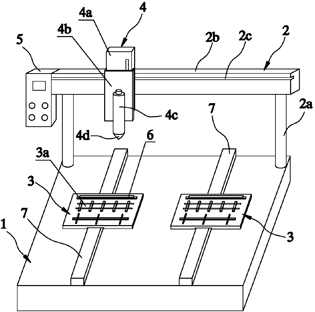
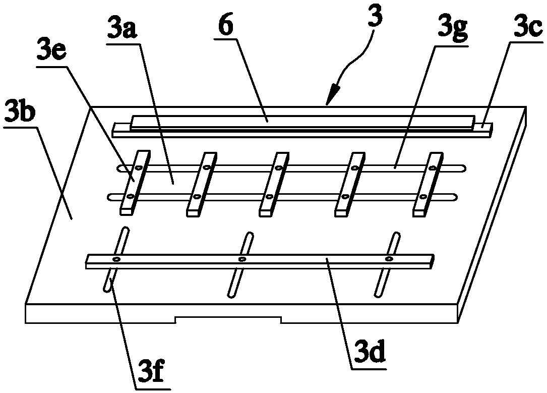
The invention discloses a novel dispensing machine, which comprises a processing platform, a frame, at least one dispensing fixture, a novel dispensing mechanism and a controller. The frame is installed at the back end of the processing platform, and the dispensing fixture can be installed on the processing platform movable back and forth. There are multiple clamping stations with adjustable positions on the dispensing fixture, and the rear of the clamping station The ends are removable with foam blocks. A new dispensing mechanism can be installed on the frame up and down, left and right, and a controller is installed on the frame and is used to control the forward and backward movement of the dispensing fixture and the up and down, left and right movement of the new dispensing mechanism. The invention controls the forward and backward movement of the dispensing fixture and the up, down, left and right movement of a new type of dispensing mechanism through the controller, thereby realizing the automatic dispensing of different positions of the mobile phone, improving the dispensing efficiency, and the rear end of the clamping station can be The disassembled one is equipped with a foam block, which can rub the residual glue on the foam block to prevent it from affecting the dispensing of subsequent products and improve the dispensing quality of the product.

Description

technical field [0001] The invention relates to the technical field of mobile phone production and processing, in particular to a novel dispensing machine for sticking mobile phone parts. Background technique [0002] In the production of mobile phone assembly, the assembly of many parts needs to be fixed by a new type of glue dispensing machine. The conventional glue dispensing method mainly uses manual glue dispensing and a new type of glue dispensing machine. The efficiency of manual glue dispensing is low. An existing new type of dispensing machine can only dispense glue at a fixed position when dispensing glue for mobile phones, and can only dispense glue for the same type of mobile phone. When dispensing glue for different positions on the mobile phone, such as When dispensing around the mobile phone screen, the above-mentioned new type of dispensing machine cannot be realized. Therefore, the function of existing mobile phone a kind of novel dispensing machine is sing...

Claims


Application Information

Patent Timeline
Patent Type & Authority Applications(China)
IPC IPC(8): B05C5/02B05C11/10B05C13/02
CPCB05C5/02B05C11/10B05C11/1039B05C13/02
Inventor 陈炳进
Owner 重庆市量劲科技有限公司
Learn More