Water guiding plate for cleaning tank

The technology of a water guide plate and a cleaning tank is applied in the field of water guide plates for cleaning tanks, which can solve the problems of clogging filter holes, troublesome cleaning, bacterial growth, etc., and achieve the effects of improving strength, avoiding sanitary dead corners, and avoiding cleaning dead corners.

Inactive Publication Date: 2018-02-09
ZHEJIANG SANFER ELECTRIC
View PDF0 Cites 0 Cited by
  • Summary
  • Abstract
  • Description
  • Claims
  • Application Information

AI Technical Summary

Problems solved by technology

At present, the cleaning tank often adopts the spraying method. Since the cleaning water is recycled, in order to prevent debris from blocking the outlet of the spraying device, a mesh plate will be installed to prevent garbage residues from entering the spraying device and only let the water pass through; when the work is completed After a program, when the water needs to be changed, the water will be discharged and the garbage will also flow, but it will block the filter hole and it is difficult to clean
Since the filter holes on the water guide plate are all in one piece, when the filter holes are located under the sprinkler device, cleaning is very troublesome, and it is easy to remain, which can easily cause the growth of bacteria

Method used


Image

  • Water guiding plate for cleaning tank
  • Water guiding plate for cleaning tank
  • Water guiding plate for cleaning tank

Examples


Embodiment 1

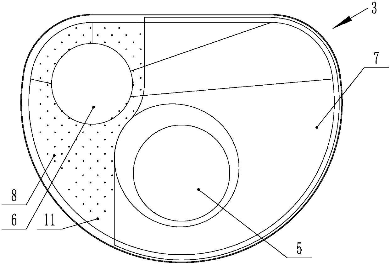
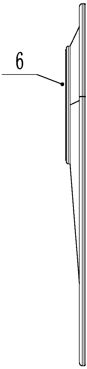
[0034] As shown in Figure 1, a first through hole 5 and a second through hole 6 are provided on the water guide plate 3, the first through hole 5 is located in the middle of the water guide plate 3, and the second through hole 6 It is located at the side of the water guide plate 3; the water guide plate 3 is divided into a light plate area 7 without filter holes 11 and a filter area 8 with filter holes 11. Wherein, the first through hole 5 matches with the cleaning device and is used for passing through the cleaning device. The second through hole 6 is opposite to the sink drain hole and is used for draining water. The local area of ​​the water guide plate 3 is perforated, and the strength of the water guide plate 3 is improved while not affecting the water launch. When a position of the cleaning device is below the bare panel area 7, since no cleaning is required, dead corners of sanitation are avoided, residue residues are reduced, and cleaning ability is improved.

[0035...

Embodiment 2

[0047] The similarities with Embodiment 1 will not be repeated, and the difference is that: figure 2 As shown, the filter hole 11 is a square hole, and its diagonal size is 0.5-1.5 mm.

Embodiment 3

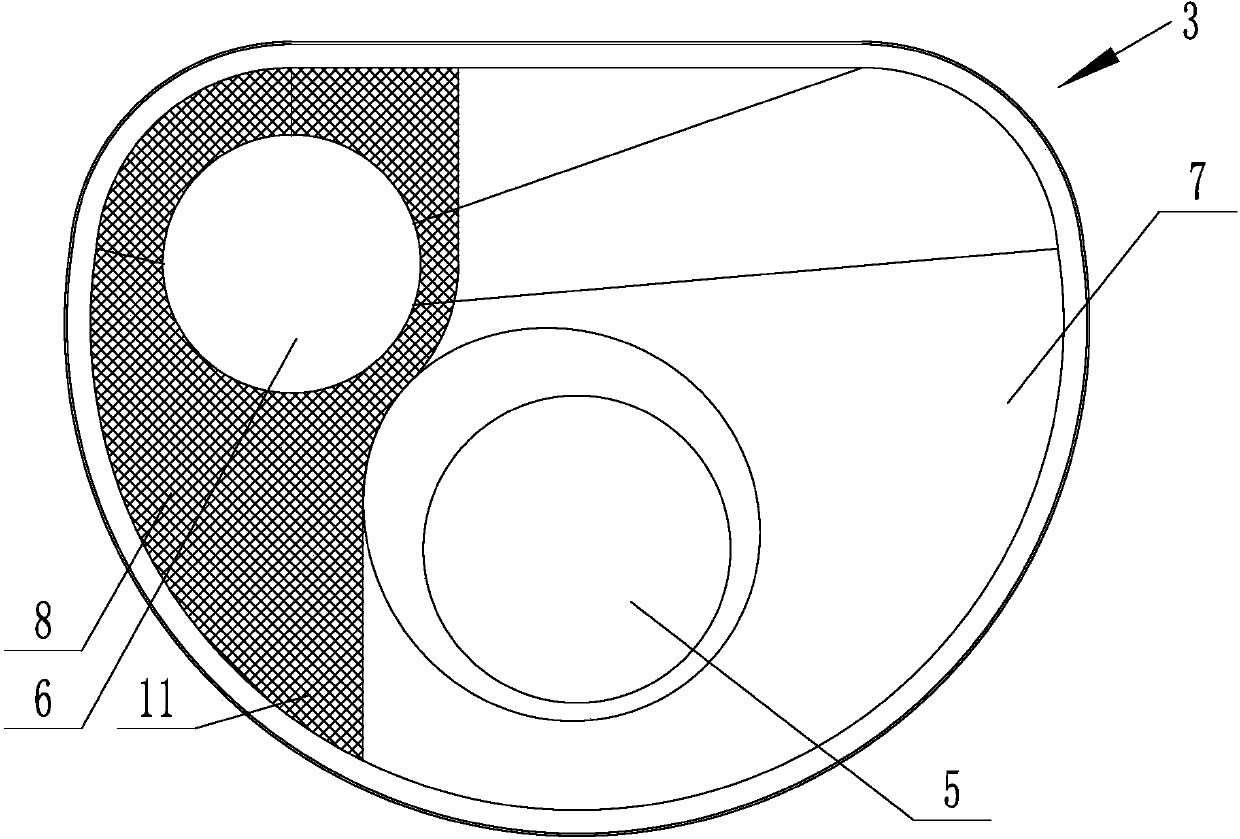
[0049] The similarities with Embodiment 1 will not be repeated, and the difference is that: image 3 As shown, the water guiding plate 3 is provided with a light plate area 7 and two filter areas 8 , and the filter areas 8 are respectively provided with two sides of the light plate area 7 .


PUM


Abstract

A water guide plate for a cleaning tank relates to a water guide plate. At present, the filter holes on the water guide plate are all over the cloth. When the filter holes are located under the spray device, it is very troublesome to clean, and it is easy to remain and cause the growth of bacteria. A first through hole and a second through hole are provided on the water guide plate of the present invention, the first through hole is located in the middle of the water guide plate, and the second through hole is located at the side of the water guide plate; The water guide plate is divided into a light plate area without filter holes and a filter area with filter holes. The partial area of ​​the water guide plate of this technical solution is perforated, and the strength of the water guide plate is improved while not affecting the water; when the cleaning device is located below a position of the light plate area, since no cleaning is required, the sanitary dead corner is avoided. Reduces residue residue and improves cleaning power.

Description

technical field [0001] The invention relates to a water guide plate, in particular to a water guide plate for a cleaning tank. Background technique [0002] Water deflectors with filter holes are widely used in different fields. They are often used for filtering and noise reduction. The size and shape of the filter holes are determined according to the filtering requirements, so as to achieve regional passage. At present, the cleaning tank often adopts the spraying method. Since the cleaning water is recycled, in order to prevent debris from blocking the outlet of the spraying device, a mesh plate will be installed to prevent garbage residues from entering the spraying device and only let the water pass through; when the work is completed After a program, when the water needs to be changed, the water will be discharged and the garbage will also flow, but it will block the filter holes and be difficult to clean. Since the filter holes on the water guide plate are all in one ...

Claims


Application Information

Patent Timeline
Patent Type & Authority Applications(China)
IPC IPC(8): B08B3/02B08B13/00B01D35/02
CPCB08B3/02B01D35/02B08B13/00
Inventor 邵于佶
Owner ZHEJIANG SANFER ELECTRIC
Why Eureka
Try Eureka